Supercharge Your Innovation With Domain-Expert AI Agents!

Drilling fluid recovery and solid control device

A drilling fluid and vacuuming device technology, applied in the field of oil drilling, can solve the problem that the mud recovery efficiency is difficult to meet the drilling construction and other problems, and achieve the effects of saving equipment purchase costs and maintenance costs, improving recovery rate, and improving screening efficiency.

Inactive Publication Date: 2016-07-20
YANGTZE UNIVERSITY
View PDF7 Cites 10 Cited by
  • Summary
  • Abstract
  • Description
  • Claims
  • Application Information

AI Technical Summary

Problems solved by technology

The existing problem is that the screening efficiency still needs to be further improved, and the mud recovery efficiency is difficult to meet the requirements of drilling construction

Method used


Image

  • Drilling fluid recovery and solid control device
  • Drilling fluid recovery and solid control device
  • Drilling fluid recovery and solid control device

Examples


Embodiment 1

[0040] In this example, the upstream and downstream are distinguished by the flow direction of the drilling fluid. One end of the drilling fluid inflow is the upstream and the other end is the downstream.

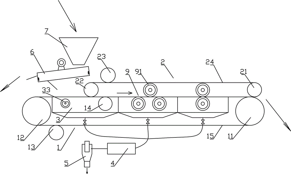
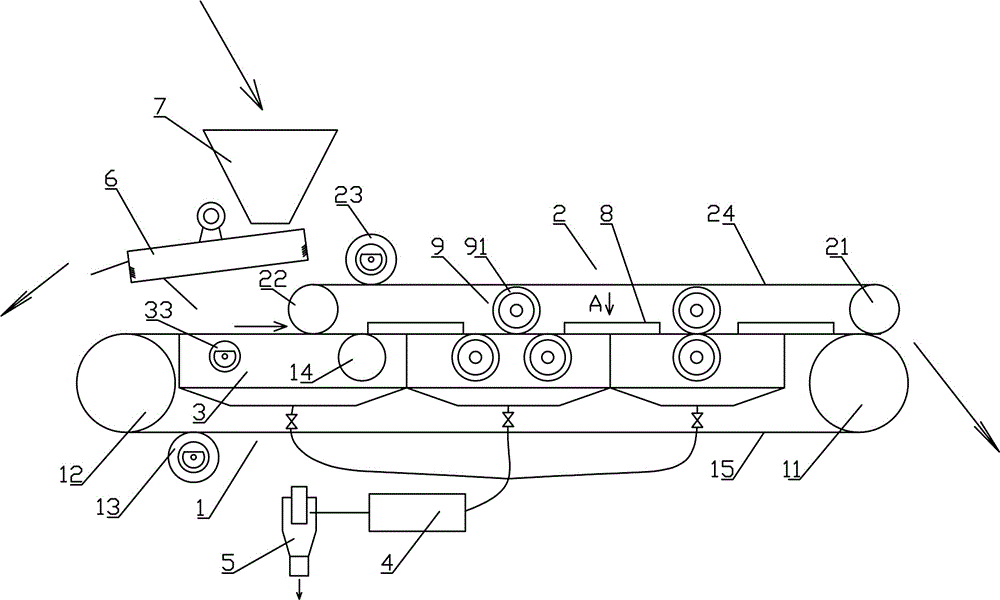
[0041] Such as figure 1 Among them, a solid control device for drilling fluid recovery, including a belt screen 1, in the belt screen 1, the belt screen 15 bypasses the belt screen driven roller 12 and the belt screen driven to rotate by the driving device The driving roller 11; the driving device is a commonly used motor, reducer and transmission mechanism, etc., which will not be described in detail here, and the driving device is not shown in the figure. Such as figure 1 , 3 Among them, the upper layer of the belt screen 15 of the belt screen 1 runs from left to right.

[0042] Such as figure 1 , 3 Among them, a belt pressing device 2 is provided above the belt screen 1;

[0043] In the described belt pressing device 2, the pressing belt 24 bypasses the belt pressi...

Embodiment 2

[0057] On the basis of Example 1, the preferred scheme is as figure 1 , 3 Among them, at least one negative pressure chamber 3 is provided under the upper layer of the belt screen 15, and the negative pressure chamber 3 is connected with the vacuum device 4. With this structure, when the drilling fluid enters between the upper layer of the belt screen 15 and the lower layer of the pressure belt 24, the vacuuming of the negative pressure chamber 3 can further improve the screening efficiency, especially suitable for high-mesh belt screens network.

[0058] preferred as figure 1 , 3 Among them, the diameter of the belt screen driving roller 11 is greater than the diameter of the pressing belt driving roller 22. With this structure, the volume of the whole device can be reduced, and it is convenient to arrange the negative pressure chamber 3 .

[0059] There are multiple negative pressure chambers 3, arranged along the upstream and downstream directions of the belt screen 15...


PUM


Abstract

The invention provides a drilling fluid recovery and solid control device. The drilling fluid recovery and solid control device comprises a belt screen, on which a press belt device is arranged; in the press belt device, a press belt surrounds a press belt driven roller and a driven device to drive a rotary press belt driving roller, and a lower layer of the press belt is in contact with an upper layer of a belt screen mesh in the belt screen; the motion directions of the lower layer of the press belt and the upper layer of the belt screen mesh are consistent; an upstream end of the upper layer of the belt screen mesh is a feeding end, and an interval is reserved between an upstream end of the lower layer of the press belt and the upstream end of the upper layer of the belt screen mesh; press rollers are arranged below the upper layer of the belt screen mesh and above the lower layer of the press belt; press roller flexible layers are arranged on the surfaces of the press rollers. By adopting the structure provided by the invention, the drilling fluid recovery and solid control device has the following beneficial effects: on the premise of less increasing the volume, screening is implemented by taking an extrusion manner instead of a vibration manner, the advantages of the belt screen and a pressure filter are combined, the screening efficiency is largely improved, the treatment quantity of drilling fluid is increased, and treatment requirements of well drilling construction can be met.

Description

technical field [0001] The invention relates to the field of petroleum drilling, in particular to a solid control device for recovery of drilling fluid. Background technique [0002] One of the development trends of drilling fluid solid control system equipment is to improve the performance of drilling fluid shale shaker as the core, simplify the existing drilling fluid shale shaker, degasser, desander, desilter, centrifuge, etc. The multi-stage solid control system, strives to replace the current multi-stage solid control system with a two-stage solid control system composed of a vibrating screen and a centrifuge under general drilling conditions. Therefore, the performance of the drilling fluid shale shaker must be improved, and the core of improving the performance of the drilling fluid shale shaker is to refine the screen. However, the drilling fluid treatment capacity of the high-mesh shale shaker is less, especially the drilling fluid treatment volume of the ultra-fin...

Claims


Application Information

Patent Timeline
IPC IPC(8): E21B21/01B07B1/10B07B1/42B07B1/46
CPCE21B21/01B07B1/10B07B1/42B07B1/46
Inventor 吕志鹏周思柱
Owner YANGTZE UNIVERSITY
Features
  • R&D
  • Intellectual Property
  • Life Sciences
  • Materials
  • Tech Scout
  • Unparalleled Data Quality
  • Higher Quality Content
  • 60% Fewer Hallucinations
Learn More