Method and system for controlling a thermal system in a vehicle

A vehicle, thermal cycle technology, used in vehicle components, hybrid vehicles, motor vehicles, etc.

Active Publication Date: 2019-12-27
FORD GLOBAL TECH LLC
View PDF3 Cites 0 Cited by
  • Summary
  • Abstract
  • Description
  • Claims
  • Application Information

AI Technical Summary

Problems solved by technology

The evaporator is configured to transfer heat from the waste heat fluid to the working fluid

Method used


Image

  • Method and system for controlling a thermal system in a vehicle
  • Method and system for controlling a thermal system in a vehicle
  • Method and system for controlling a thermal system in a vehicle

Examples


Embodiment Construction

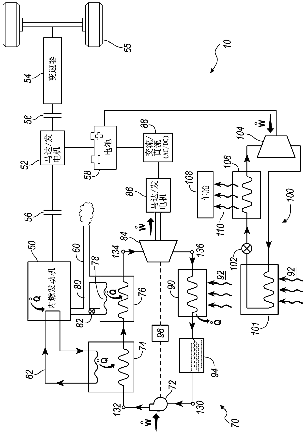
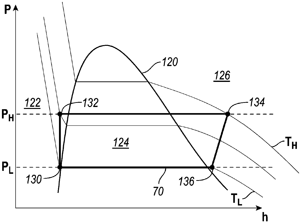
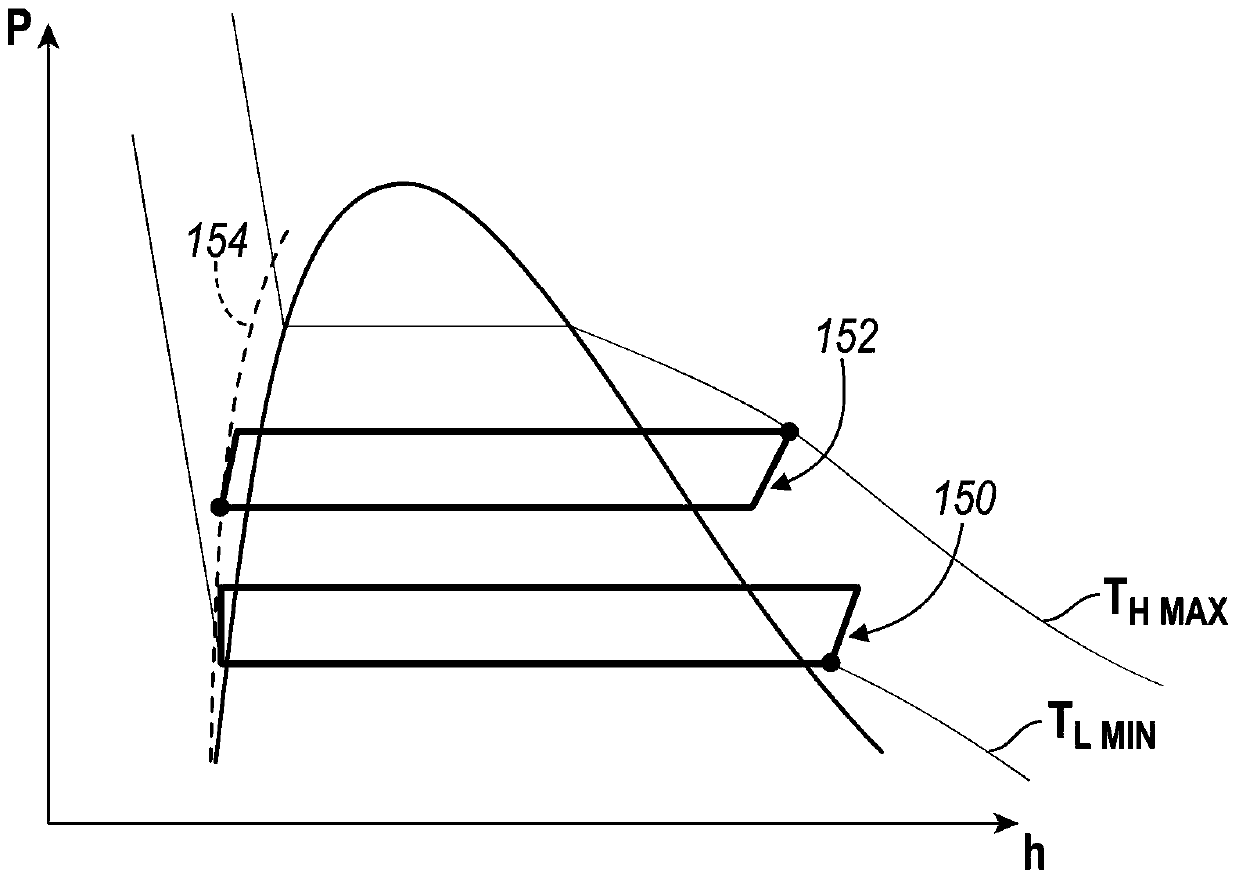
[0012] As required, specific embodiments of the invention are disclosed in the specification; however, it is to be understood that the disclosed embodiments are merely exemplary of the invention which may be embodied in various and alternative forms. The figures are not necessarily to scale; some features may be exaggerated or minimized to show details of particular components. Therefore, specific structural and functional details disclosed herein are not to be interpreted as limiting, but merely as a representative basis for teaching one skilled in the art to variously employ the present invention. Components described in chemical terms refer to the components when added to any of the combinations specified in this specification and do not necessarily exclude chemical interactions between the components of the mixture once the mixture has been mixed. Fluids as described herein may refer to substances in various states or phases including vapor phase, liquid phase, mixed vapor...


PUM


Abstract

A vehicle has a vehicle system with a waste heat fluid. An expander, a condenser, a pump, and an evaporator are provided in sequential fluid communication in a thermodynamic cycle containing a working fluid. The evaporator is configured to transfer heat from the waste heat fluid to the working fluid. At least one valve adjacent to the pump is controlled to control fluid flow through at least one chamber to maintain a pressure of the fluid at a pump inlet at a threshold pressure above a saturated vapor pressure associated with a temperature at a condenser outlet when ambient temperature varies.

Description

technical field [0001] Various embodiments relate to controlling a thermal system in a vehicle for waste heat energy recovery, such as a Rankine cycle. Background technique [0002] Vehicles, including hybrid vehicles, have internal combustion engines that generate high temperature exhaust gas. Vehicles may also have systems that have waste heat and require cooling, such as an engine coolant system with coolant fluid. A thermodynamic cycle, such as a Rankine cycle, may be used to recover waste heat within the vehicle during operation using a heat exchanger. This cycle may need to be controlled to meet predetermined operating parameters, and this can be challenging for vehicle applications where the ambient environment is variable. Contents of the invention [0003] In one embodiment, a vehicle having a vehicle system with waste heat fluid is provided. An expander, condenser, pump and evaporator are provided in sequential fluid communication in a thermodynamic cycle cont...

Claims


Application Information

Patent Timeline
Patent Type & Authority Patents(China)
IPC IPC(8): F02G5/00F01K25/00B60H1/00
CPCB60H1/004B60H1/00492F01K25/00F02G5/00F01K23/065F01K23/101Y10S903/904B60R16/08F01N5/02Y02T10/12
Inventor 周时光
Owner FORD GLOBAL TECH LLC
Why Eureka
Try Eureka