
Pneumatic vacuum generator

A vacuum generator and air pressure technology, which is applied in the direction of machines/engines, non-displacement pumps, mechanical equipment, etc., can solve the problems of difficult control of vacuum degree, high energy consumption, heavy weight, etc., and achieve small surface leakage and adsorption volume The effect of small, low-cost manufacturing

Inactive Publication Date: 2016-07-20
JIANGSU SHUANGNENG SOLAR ENERGY
View PDF6 Cites 3 Cited by
  • Summary
  • Abstract
  • Description
  • Claims
  • Application Information

AI Technical Summary

Problems solved by technology

[0002] Pneumatic vacuum generators are widely used in broadcasting, communication, television, radar, navigation, industrial automation, machinery, electronics, packaging, printing, plastics and robots. Pneumatic vacuum generators need to absorb and transport various materials, especially suitable for To absorb fragile, soft, thin non-ferrous, non-metallic materials or spherical objects, ordinary air pressure vacuum generators use vacuum pumps driven by motors, which generate large energy consumption, large volume, heavy weight and require regular maintenance
[0003] In addition, in the application process, the ordinary air pressure vacuum generator is not stable due to the unstable pumping volume, the vacuum degree is difficult to control, and the intermittent time is not accurate during intermittent work, resulting in inaccurate action of the air pressure vacuum generator.

Method used


Image

  • Pneumatic vacuum generator

Examples


Embodiment Construction

[0016] The following examples can enable those skilled in the art to understand the present invention more comprehensively, but the present invention is not limited to the scope of the described examples.

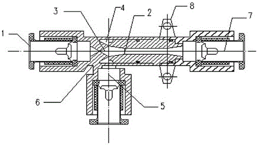
[0017] like figure 1 The innovation of the air pressure vacuum generator shown is that the air pressure vacuum generator includes an exhaust port 1, a Laval nozzle 2, a nozzle 3, a negative pressure chamber 4, a vacuum port 5, a housing 6 and an air inlet 7;

[0018] The exhaust port 1, the nozzle 3, the negative pressure chamber 4, the Laval nozzle 2, and the air inlet 7 are sequentially arranged in the air pressure vacuum generator housing 6, and the Laval nozzle 2 and the exhaust port 1 are connected through the nozzle 3 , a vacuum port 5 is installed in the vertical direction of the nozzle 3, the negative pressure chamber 4 is located at the interface between the Laval nozzle 2 and the nozzle 3, and the air inlet 7 is connected to one end of the Laval nozzle 2;

[001...


PUM


Abstract

The invention relates to a pneumatic vacuum generator. The pneumatic vacuum generator is characterized by comprising an air outlet, a laval nozzle, a spray nozzle, a negative-pressure cavity, a vacuum port, a shell and an air inlet. According to the pneumatic vacuum generator, compressed air serves as power, the compressed air can enter the airflow spray nozzle, airflow flows out of the spray nozzle at a high speed, the air suction effect is achieved, and finally the compressed air and sucked air are discharged into the atmosphere through a receiver spray nozzle. The pneumatic vacuum generator with the design is simple in structure, low in manufacturing cost, small in absorption volume, short in response time, small in surface leakage amount and low in air consumption.

Description

technical field [0001] The invention relates to a vacuum device, in particular to a pneumatic vacuum generator. Background technique [0002] Pneumatic vacuum generators are widely used in broadcasting, communication, television, radar, navigation, industrial automation, machinery, electronics, packaging, printing, plastics and robots. Pneumatic vacuum generators need to absorb and transport various materials, especially suitable for To absorb fragile, soft, thin non-ferrous, non-metallic materials or spherical objects, ordinary air pressure vacuum generators use vacuum pumps driven by motors, which consume a lot of energy, are large in size, heavy in weight and require regular maintenance. [0003] In addition, in the application process, the ordinary air pressure vacuum generator is not stable due to the unstable pumping volume, the vacuum degree is difficult to control, and the intermittent time during intermittent work is not accurate, resulting in inaccurate action of t...

Claims


Application Information

Patent Timeline
IPC IPC(8): F04F5/20F04F5/44
CPCF04F5/20F04F5/44
Inventor 贲道祥
Owner JIANGSU SHUANGNENG SOLAR ENERGY
Learn More