Thermal storage type combustion furnace and working method

A working method and combustion furnace technology, applied in the field of combustion furnaces, can solve problems such as restricting popularization and use, and achieve the effects of improving furnace temperature uniformity, reasonable structure design, and reducing NOX concentration

Inactive Publication Date: 2016-07-20
TIANJIN RANDYS IND EQUIP
View PDF0 Cites 5 Cited by
  • Summary
  • Abstract
  • Description
  • Claims
  • Application Information

AI Technical Summary

Problems solved by technology

However, due to high temperature combustion brings high NO X emissions, thus limiting its promotion and use in industrially developed countries

Method used


Image

  • Thermal storage type combustion furnace and working method

Examples


Embodiment Construction

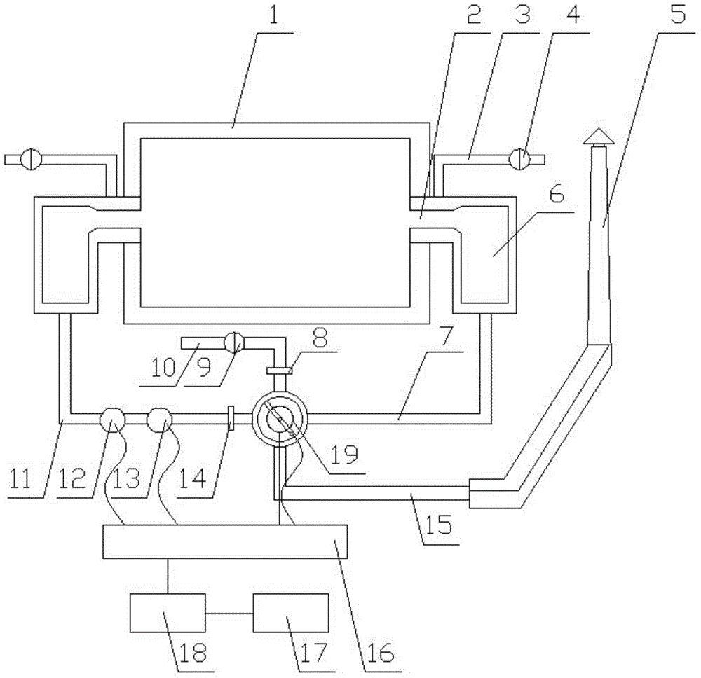
[0010] refer to figure 1 , the regenerative combustion furnace includes a combustion furnace 1 and two symmetrical regenerators 6, each regenerator 6 is provided with a gas pipe 3 with a switch valve 4, and the regenerator 6 is connected to the combustion chamber through a burner 2 Furnace 1, one of the regenerators 6 is connected to the intake pipe B7, the other end of the intake pipe B7 is connected to the reversing valve 9, the other regenerator 6 is connected to the exhaust pipe A11, and the other end of the exhaust pipe A11 is connected to the reversing valve 9. The reversing valve 9 is also connected with the intake pipe A10 and the exhaust pipe B15. The reversing valve 9 is a single-control double-opening type. The reversing valve 9 is equipped with a video collector, and the exhaust pipe A11 is also equipped with a furnace pressure Detector 12 and smoke temperature detector 13, furnace pressure detector 12, smoke temperature detector 13 and video collector are all conn...


PUM


Abstract

The invention belongs to the technical field of combustion furnaces and provides a thermal storage type combustion furnace and a working method. The thermal storage type combustion furnace comprises a combustion furnace body and two symmetrical thermal storage chambers. Each thermal storage chamber is provided with a fuel gas pipe with a switch valve. The thermal storage chambers are connected with the combustion furnace body through burners. One thermal storage chamber is connected with a gas inlet pipe B, and the other end of the gas inlet pipe B is connected with a reversing valve. The other thermal storage chamber is connected with a smoke exhaust pipe A, and the other end of the smoke exhaust pipe A is connected with the reversing valve. The reversing valve is further connected with a gas inlet pipe A and a smoke exhaust pipe B. A video collector is arranged in the reversing valve. A hearth pressure detector and a smoke temperature detector are further arranged on the smoke exhaust pipe A. The hearth pressure detector, the smoke temperature detector and the video collector are all connected with a signal processor. The signal processor is connected with a programmable logic controller (PLC). The PLC is connected with a thick film transistor (TFT) and an alarm device, and meanwhile the PLC controls reversing of the reversing valve. The thermal storage type combustion furnace and the working method have the following beneficial effects that 1, energy is saved; 2, the furnace temperature uniformity is improved; 3, the heat transfer efficiency is improved; 4, the concentration of NOx is reduced; and 5, the structural design is reasonable, and the conception is ingenious and novel.

Description

Technical field: [0001] The invention belongs to the technical field of combustion furnaces, and in particular relates to a regenerative combustion furnace and a working method. Background technique: [0002] With the continuous advancement of economic globalization, resource and environmental issues have become increasingly prominent. As industrial furnaces are a large energy consumer, how to implement efficient and environmentally friendly energy-saving technologies as soon as possible has become a top priority. The main purpose of adopting the regenerative burner in the early stage is to further increase the preheating temperature of the air, recover the heat taken away by the flue gas to a greater extent, and save energy. However, due to high temperature combustion brings high NO X emissions, thus limiting its promotion and use in industrially developed countries. Invention content: [0003] The object of the present invention is to provide a regenerative combustion ...

Claims


Application Information

Patent Timeline
IPC IPC(8): F23D14/66
CPCY02E20/34
Inventor 尚仲为
Owner TIANJIN RANDYS IND EQUIP
Why Eureka
Try Eureka