Rotating electric machine control device

A technology for rotating electrical machines and control devices, which is applied in motor control, AC motor control, control systems, etc., and can solve problems such as control without description

Active Publication Date: 2016-07-20
DENSO CORP
View PDF8 Cites 11 Cited by
  • Summary
  • Abstract
  • Description
  • Claims
  • Application Information

AI Technical Summary

Problems solved by technology

[0003] However, Patent Document 1 does not describe control in the case of, for example, a short-circuit failure in a switching element constituting an inverter

Method used


Image

  • Rotating electric machine control device
  • Rotating electric machine control device
  • Rotating electric machine control device

Examples


no. 1 approach

[0020] Figure 1 to Figure 3 A rotating electric machine control device according to a first embodiment of the present disclosure is shown. The rotating electric machine control device 1 of the present embodiment is applied to an electric power steering apparatus 5 for assisting a driver's steering operation together with an electric motor 10 as a rotating electric machine.

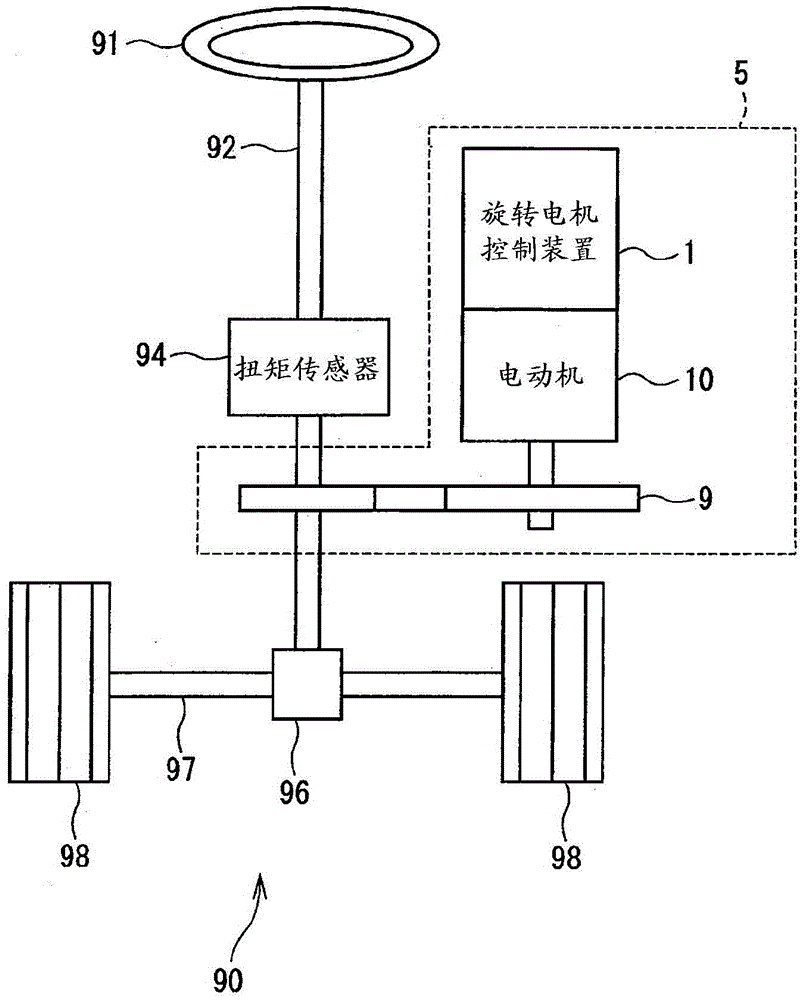
[0021] figure 1 An overall configuration of a steering system 90 provided with the electric power steering device 5 is shown. The steering system 90 has a steering wheel 91 , a steering shaft 92 , a pinion 96 , a rack shaft 97 , wheels 98 , an electric power steering device 5 , and the like.

[0022] The steering wheel 91 is connected to a steering shaft 92 . The steering shaft 92 is provided with a torque sensor 94 for detecting a steering torque input by the driver operating the steering wheel 91 . The pinion gear 96 is provided at the tip of the steering shaft 92 and meshes with the rack shaft 97 ....

no. 2 approach

[0101] will refer to Figure 4 A second embodiment of the present disclosure will be described.

[0102] The control unit 42 of the present embodiment includes a command calculation unit 53 , a second disturbance voltage estimator 71 , a bandpass filter 73 , a second current estimator 75 , and a three-phase to two-phase conversion unit 77 .

[0103] The command calculation section 53 has: a three-phase to two-phase conversion section 510, current command value correction sections 531, 532, subtractors 533, 534, controllers 514, 515, dq non-alternative voltage calculation sections 516, 517, non-alternative voltage correction Sections 518 and 519, a two-phase to three-phase conversion section 520, and disturbance voltage correction sections 541, 542, and 543.

[0104] The d-axis current command value correcting section 531 adds the d-axis second current command value Id_f2 and the d-axis current command value Id* to calculate the corrected d-axis current command value Id**, whi...

no. 3 approach

[0153] will refer to Figure 5 A third embodiment of the present disclosure will be described. The difference is that the d-q axis voltage equation is used in the present embodiment, whereas the three-phase voltage equation is used in the second embodiment. Using the d-q axis model instead of the three-phase model allows the number of arithmetic expressions to be reduced.

[0154] as in Figure 5 As shown in , the control unit 43 has: a command calculation unit 55 , a second disturbance voltage estimator 72 , a bandpass filter 74 , and a second current estimator 76 .

[0155]The command calculation section 55 has: a three-phase to two-phase conversion section 510, current command value correction sections 531, 532, subtractors 533, 534, controllers 514, 515, dq non-alternative voltage calculation sections 516, 517, non-alternative voltage correction Sections 518, 519, interference voltage correction sections 551, 552, and two-phase to three-phase conversion section 553.

...


PUM


Abstract

A rotating electric machine control device includes: an inverter (21, 22) in each winding set (11, 12) of a rotating electric machine (10) having high and low potential-side switching elements (211-216, 221-226) corresponding to each phase; and a controller (41-45). The controller has: a signal generator (48) of a control signal for turning on and off the high and low potential-side switching elements; a disturbance voltage estimating device (62, 71, 72) calculating a disturbance voltage estimation value of a disturbance voltage, which is generated in a normal system, based on a current flowing in a failure system when the short circuit failure occurs; and a command calculating device (51, 53, 55, 56, 57) calculating a normal system command value in accordance with the disturbance voltage estimation value.

Description

technical field [0001] The present disclosure relates to rotating electric machine controls. Background technique [0002] Hitherto, there has been known a multi-winding motor control device that controls a multi-winding motor having a plurality of windings in one motor by using a plurality of inverters. For example, Patent Document 1 proposes control that compensates for interference between current control systems of respective windings so that they are in a non-interfering state. [0003] However, Patent Document 1 does not describe control in a case where, for example, a short-circuit fault occurs in a switching element constituting an inverter. [0004] Patent Document 1: JP2003-153585A (corresponding to US2003 / 0085683) Contents of the invention [0005] An object of the present disclosure is to provide a rotating electric machine control device that appropriately controls the driving of the rotating electric machine even when a short-circuit fault partially occurs....

Claims


Application Information

Patent Timeline
Patent Type & Authority Applications(China)
IPC IPC(8): H02P29/028H02P25/22
CPCH02P25/22H02P29/032H02P21/14H02P27/06H02P29/028
Inventor 铃木崇志
Owner DENSO CORP
Why Eureka
Try Eureka