Eureka AIR delivers breakthrough ideas for toughest innovation challenges, trusted by R&D personnel around the world.

Thin heat pipe having wicks of crisscross structure

A liquid absorbing core and heat pipe technology, applied in the direction of tubular elements, heat exchange equipment, heat exchanger shells, etc., can solve the problems of loss of working fluid, increase of thermal resistance of heat pipe 201, and improvement of productivity, etc., to reduce flow resistance, The effect of improving discharge efficiency and improving production efficiency

Inactive Publication Date: 2016-07-20
TTM
View PDF7 Cites 3 Cited by
  • Summary
  • Abstract
  • Description
  • Claims
  • Application Information

AI Technical Summary

Problems solved by technology

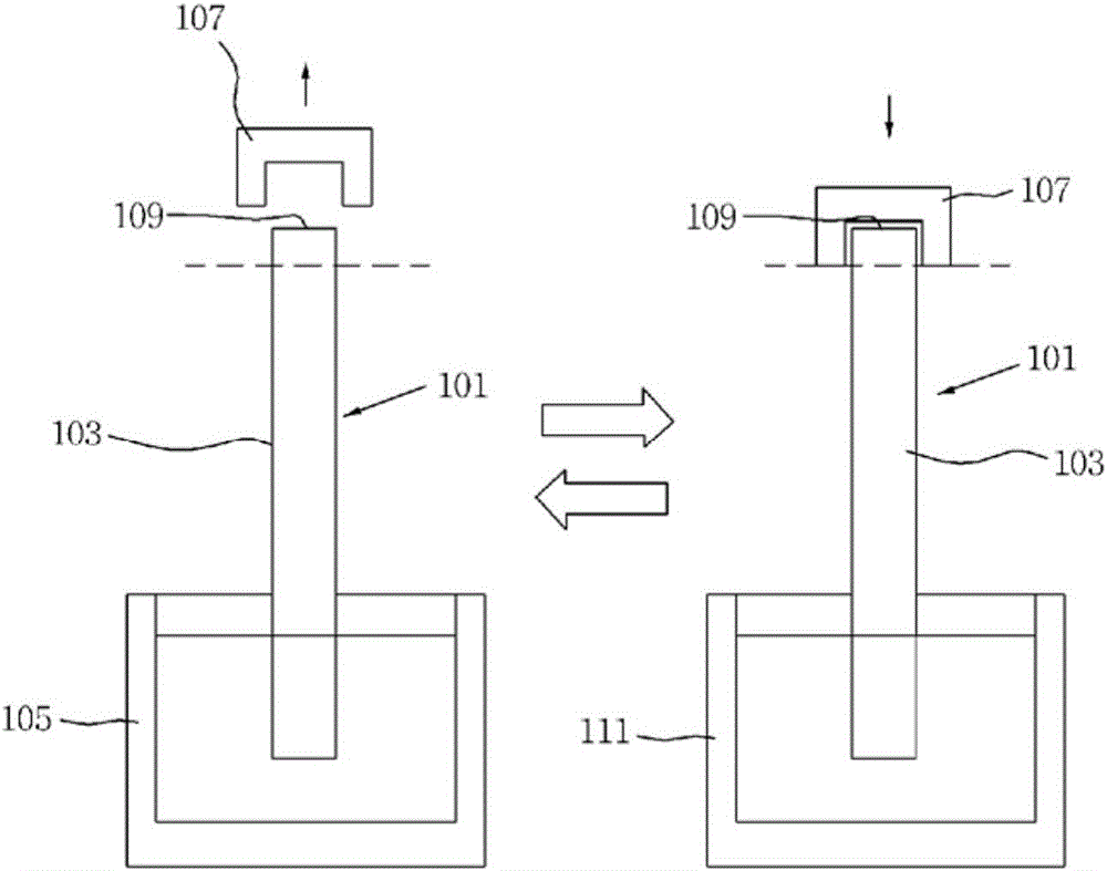
[0013] Therefore, the liquid-phase and gas-phase working fluid that expands in the housing 103 during heating are discharged to the outside together with the non-condensable gas through the wide inlet 109, so that only the non-condensable gas cannot be selectively removed, and the working fluid that is discharged together Not only will it surge irregularly at the injection port 109 and become uncontrollable, but also a larger amount of working fluid than the allowable range will be lost to the outside, making it difficult to meet the proper amount of working fluid required for the heat pipe 101.
[0014] In addition, as mentioned above, in order to prevent the loss of the working fluid caused by a large amount of working fluid being discharged together with the non-condensable gas, it is necessary to limit the opening time of the injection port 109 during heating, so that the non-condensable gas cannot be fully discharged. The same heating and cooling process is repeated to discharge non-condensable gas, so the process time is prolonged, and the improvement of productivity in mass production is limited
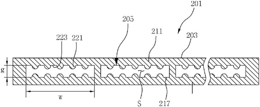
[0015] In particular, if figure 2 As shown, when the heat pipe 201 is made into a thin shape, in the working space S of the housing 203, the proportion of the liquid-absorbing core 205 is relatively increased, so the interval g of the injection port 217 of the housing 203 is important for absorbing liquid. The protrusions 221 of the core 205 are greatly narrowed, and are greatly widened between the grooves 223. When the distance between the injection ports 217 is adjusted based on the distance between the protrusions 221, there is a gap between the grooves 223 during exhaust. If the working fluid between the protrusions 221 is too narrow and the space between the protrusions 221 becomes too narrow, there will be working fluid in the liquid phase. The problem that the flow resistance of the heat pipe 201 increases due to the increase of the flow resistance
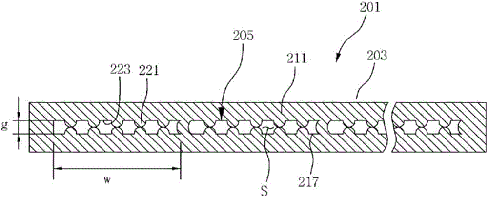
[0016] In addition, if image 3 As shown, in the process of sealing the injection port 217 by stamping or the like after exhausting, the upper and lower protrusions 221 first contact to delay the sealing of the injection port 217, that is, the interval between the groove 223 and the groove, resulting in a The sealing work of the injection port 217, which is completed quickly after the air is exhausted, becomes longer, and the loss of the working fluid cannot be accurately adjusted, resulting in a problem that the quality of the heat pipe 1 deteriorates.

Method used


Image

  • Thin heat pipe having wicks of crisscross structure
  • Thin heat pipe having wicks of crisscross structure
  • Thin heat pipe having wicks of crisscross structure

Examples


Embodiment Construction

[0037] Hereinafter, a thin heat pipe having liquid-absorbing wicks with a staggered structure according to an embodiment of the present invention will be described in detail with reference to the accompanying drawings.

[0038] Such as Figure 4 to Figure 7 Denoted by reference numeral 1 in the middle, the heat pipe of the present invention generally includes a casing 3 , a working fluid and a liquid-absorbing wick 5 .

[0039] Here, firstly, the casing 3 is a part that constitutes the outer body of the heat pipe 1, such as Figure 4 As shown, the housing 3 includes: a pair of flat bodies 11, which are arranged oppositely up and down in the figure; a pair of side walls 13, which are connected to the sides of the flat bodies 11 The left and right sides; the rear wall body, which is not shown in the figure, is used to connect the rear end of the plate body 11; the final processing end, the final processing end is located in the front, and is used for final processing by stampin...


PUM


Abstract

The present invention relates to a thin heat pipe having wicks of a crisscross structure, the thin heat pipe comprising: a housing (3) constituting a plate-shaped outer body having a thickness smaller than the length or width thereof; an operating fluid evaporated at an evaporation portion on one side of the housing (3) and then condensed at a condensation portion on the other side thereof, thereby transferring heat from the evaporation portion to the condensation portion; and wicks (5) extending in the longitudinal direction such that the operating fluid, which has been condensed at the condensation portion, returns to the evaporation portion, wherein the wicks (5) are arranged on inner peripheral surfaces of respective flat plate bodies (11) so as to crisscross each other in the transverse direction such that the flow sectional area of an operating space (S) is maintained to be constant in the transverse direction; as a result, a sufficient sectional area of an injection opening for degassing is secured, and the boiling operating fluid is prevented from being discharged in a liquid lump state, thereby enabling expectation of improving the heat pipe quality and production efficiency.

Description

technical field [0001] The present invention relates to a heat pipe, and more specifically, relates to a heat pipe in which the working fluid condensed in the condensing part is recycled to the heat generating part by arranging the liquid-absorbing cores arranged vertically and vertically in the interior of the housing in a staggered manner. In the process, the yield of the working fluid is improved, and the production efficiency is improved. Background technique [0002] Generally speaking, the thermal conductivity of a heat pipe is tens to hundreds of times greater than that of high thermal conductivity metals such as silver, copper, and aluminum. Therefore, the application range of the heat pipe is very wide, and it is a kind of situation that can be applied to the situation that needs to cool the heat-generating part of a specific position, such as the CPU of the computer, the situation that needs to recover the heat of the exhaust gas, and the situation of collecting ge...

Claims


Application Information

Patent Timeline
IPC IPC(8): F28D15/02F28F9/00
CPCF28D15/0233F28D15/0283F28D15/046F28F1/022F28D15/02F28F3/02F28F9/00
Inventor 车浚先金炳镐崔有镇
Owner TTM
Why Eureka
Eureka Blog
Learn More