
Bi-directional cutting slitting equipment

A kind of equipment and cutting knife technology, applied in metal processing and other directions, can solve the problems of cutting knife working wear, cutting knife damage, increasing probability, etc., to achieve the effect of stable machine operation, reducing wear and improving service life

Inactive Publication Date: 2016-07-27
TAICANG ZHONGHOU MECHANICS CO LTD
View PDF6 Cites 3 Cited by
  • Summary
  • Abstract
  • Description
  • Claims
  • Application Information

AI Technical Summary

Problems solved by technology

[0002] In the packaging industry, roll paper, labels, thin packaging metal sheets, and tapes need to process large-diameter materials and cut them into smaller materials. In this case, slitter equipment is required. The existing slitter During the operation of the equipment, the noise is large, and the cutting knife is seriously worn. After a long time of use, the cutting circular knife needs to be replaced regularly. Moreover, in the existing technology, the workpiece material does not rotate, and the circular saw blade rotates again, making the circular saw During the high-speed rotation of the knife, the probability of hitting the support shaft of the material increases, causing the cutting knife to be damaged. For this reason, the present invention provides a two-way cutting and slitting device. During work, the circular saw knife does not rotate, and the workpiece material is The knife rotates, and at the same time, the cut rolls and labels are neat and orderly

Method used


Image

  • Bi-directional cutting slitting equipment

Examples


Embodiment Construction

[0018] The preferred embodiments of the present invention will be described in detail below in conjunction with the accompanying drawings, so that the advantages and features of the present invention can be more easily understood by those skilled in the art, so as to define the protection scope of the present invention more clearly.

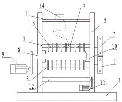
[0019] see figure 1 , the embodiment of the present invention includes:

[0020] The two-way cutting and slitting device includes a base, the base adopts a cuboid structure, and the material is made of cast iron, and two support columns are respectively arranged on the base, the support columns are made of alloy steel, and the support columns adopt a cuboid structure .

[0021] Connecting beams, upper cutting knife main shaft, workpiece discharging shaft, lower cutting knife main shaft, material receiving shaft, the connecting beam, upper cutting knife main shaft, workpiece discharging shaft, and lower cutting knife main shaft are respectively a...


PUM


Abstract

The invention discloses bi-directional cutting slitting equipment. The bi-directional cutting slitting equipment comprises a base; two vertical supporting posts are arranged on the base; a connection cross beam, an upper cutter knife spindle, a workpiece material placing shaft, a lower cutter knife spindle and a material receiving shaft are arranged between the vertical supporting posts from top to bottom in sequence. According to the bi-directional cutting slitting equipment, cutter knives do not directly make contact with a material spindle in the using process, so that operation of the machine is smooth and steady, the cutter knife abrasion times is decreased, the service life is prolonged, the mass of the slitting equipment is uniform, and the phenomena of burrs and folds are avoided.

Description

technical field [0001] The invention relates to the field of slitting machinery, in particular to bidirectional cutting and slitting equipment. Background technique [0002] In the packaging industry, roll paper, labels, thin packaging metal sheets, and tapes need to process large-diameter materials and cut them into smaller materials. In this case, slitter equipment is required. The existing slitter During the operation of the equipment, the noise is large, and the cutting knife is seriously worn. After a long time of use, the cutting circular knife needs to be replaced regularly. Moreover, in the existing technology, the workpiece material does not rotate, and the circular saw blade rotates again, making the circular saw During the high-speed rotation of the knife, the probability of hitting the support shaft of the material increases, causing the cutting knife to be damaged. For this reason, the present invention provides a two-way cutting and slitting device. During work...

Claims


Application Information

Patent Timeline
Patent Type & Authority Applications(China)
IPC IPC(8): B26D1/36B26D1/40B26D5/12B26D7/26
CPCB26D1/365B26D1/405B26D5/12B26D7/2614
Inventor 郭江龙
Owner TAICANG ZHONGHOU MECHANICS CO LTD
Learn More