Low-nitrogen energy-saving combustion unit of combustor

A combustion unit and burner technology, which is applied to burners, gas fuel burners, combustion methods, etc., can solve problems such as unevenness, low combustion efficiency, and long residence time of nitrogen molecules, achieve uniform temperature field distribution, and improve thermal efficiency. Remarkable effect of exchange rate and emission reduction effect

Active Publication Date: 2016-07-27
北京中宇先创能源科技有限公司
View PDF6 Cites 4 Cited by
  • Summary
  • Abstract
  • Description
  • Claims
  • Application Information

AI Technical Summary

Problems solved by technology

The air supply pipe nozzle of the combustion unit of the existing burner is arranged in parallel with the gas pipe nozzle or communicated in the combustion head, and the gas and air are ejected from the nozzles at the front ends of the respective pipes. The main disadvantage of the structure is that the mixing is insufficient and uneven, and the combustion efficiency is low; the second is that the flame velocity at the outlet of the combustion unit is low, and the nitrogen molecules stay in the combustion chamber for a long time, resulting in high nitrogen oxides; the third is that the precise ratio cannot be achieved (The optimal ratio of gas and air is 1﹤α﹤1.1, α is the ratio coefficient), so that when the air is insufficient, the excess gas will be decomposed into free carbon, nitrogen, carbon monoxide, the utilization rate of gas is low, and a large amount of gas will be generated at the same time Carbon monoxide harmful gas and free carbon emissions, when the air is excessive, the excess air will take away heat and produce excessive nitrogen oxide emissions, resulting in heat loss

Method used


Image

  • Low-nitrogen energy-saving combustion unit of combustor
  • Low-nitrogen energy-saving combustion unit of combustor
  • Low-nitrogen energy-saving combustion unit of combustor

Examples


Embodiment Construction

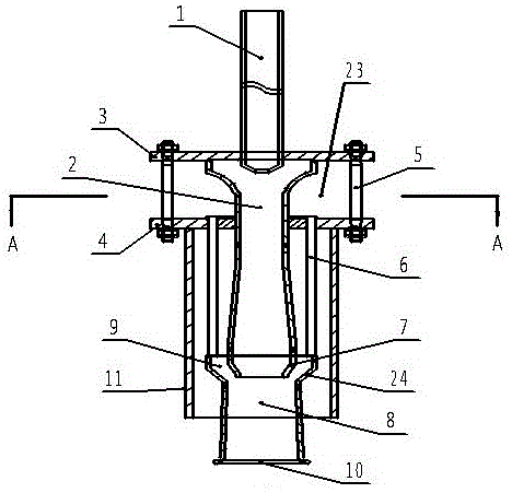
[0012] as attached figure 1 As shown, the diffusion throat mixing chamber 2 is in the shape of a cylinder as a whole, and its rear part is fixed by an air partition 3 and a flange 4. The rear end of the diffusion throat mixing chamber 2 communicates with the primary air distribution chamber 20, and the diffusion throat The middle and front parts of the mixing chamber 2 are fixed in the cylindrical shell 11, and the diffusion throat mixing chamber 2 is composed of three cones from the back to the front (the gas movement direction is the front), and the first cone is mixed in the diffusion throat. At the rear of chamber 2, the diameter gradually decreases from the rear end of the diffusion throat mixing chamber 2 to the front; the second conical shape is in the middle of the diffusion throat mixing chamber 2, and the diameter gradually increases from the rear to the front; the third conical shape That is, the front end outlet of the diffuser throat mixing chamber 2 shrinks inwar...


PUM


Abstract

The invention discloses a low-nitrogen energy-saving combustion unit of a combustor. The low-nitrogen energy-saving combustion unit of the combustor comprises a cylindrical shell and a diffusion throat pipe mixing chamber. The front portion of the diffusion throat pipe mixing chamber is arranged in the cylindrical shell. The low-nitrogen energy-saving combustion unit of the combustor is characterized in that the front end of the diffusion throat pipe mixing chamber is conical, and a conical cover is installed in front of a conical shrinkable throat pipe; an annular gap air duct is formed between the outer wall of the conical shrinkable throat pipe and the inner wall of the conical cover; a secondary air pipe communicates with the annular gap air duct; and a conical combustion nozzle is fixed to the front end of the conical cover. By the adoption of the structure, gas can be combusted twice, and the speed of a flame sprayed out of the cylindrical combustion nozzle is high, so that sufficient stirring is achieved in a furnace, the temperature field distribution in the furnace is uniform, and the heat exchange rate is increased; and the energy can be saved by 10% or over by the adoption of the low-nitrogen energy-saving combustion unit. According to the low-nitrogen energy-saving combustion unit of the combustor, the discharge of oxynitride is lower than 40 mg/m<3> and is much lower than the national standard, and the energy saving and emission reduction effects are extremely remarkable.

Description

technical field [0001] The invention relates to a burner for an industrial chemical heating furnace using combustible gas as fuel. Background technique [0002] The burner is a device that provides heat energy to the heating furnace. A heating furnace is equipped with multiple burners, and the combustible gas is injected into the furnace from the burner nozzle to make the temperature in the furnace meet the process requirements. The combustion unit is the main part of the burner. A burner is composed of multiple combustion units. The combustion state of the combustion unit determines the energy saving and emission reduction of the burner and even the entire heating furnace. The air supply pipe nozzle of the combustion unit of the existing burner is arranged in parallel with the gas pipe nozzle or communicated in the combustion head, and the gas and air are ejected from the nozzles at the front ends of the respective pipes. The main disadvantage of the structure is that the ...

Claims


Application Information

Patent Timeline
Patent Type & Authority Applications(China)
IPC IPC(8): F23D14/02F23D14/62F23D14/46
CPCF23D14/02F23D14/46F23D14/62F23D2203/007
Inventor 穆瑞力
Owner 北京中宇先创能源科技有限公司
Why Eureka
Try Eureka