A light field deflection measurement system and method for a highly reflective object surface

A technology of object surface and measurement system, applied in measurement devices, optical devices, instruments, etc., can solve problems such as reducing measurement accuracy, solving 'non-unique, non-occurring normal lines, etc., to achieve convenient light field decoding and light identification. , the effect of high response characteristics

Active Publication Date: 2019-02-22
SHANGHAI UNIV
View PDF5 Cites 1 Cited by
  • Summary
  • Abstract
  • Description
  • Claims
  • Application Information

AI Technical Summary

Problems solved by technology

[0004] The phase deflection measurement system composed of a single projection device and a CCD camera has the disadvantage of solving the problem of 'non-unique normal', and the measurement system has a large error
At present, a variety of solutions based on phase deflection technology have been proposed to realize the topography measurement of the surface of highly reflective objects, but there are certain deficiencies.
For example, the measurement system proposed by Markus C.Knauer abroad is composed of LCD and two CCD cameras. The disadvantage is that the use of two cameras increases the cost; the measurement system proposed by Xiao Yongliang of Sichuan University consists of two LCD displays and a CCD camera. The disadvantage is that The positional relationship between CCD and LCD is not easy to calibrate; the measurement system proposed by Tao Tao of Shanghai University consists of an LCD display and a CCD camera placed on a precision guide rail. The disadvantage is that the auxiliary guide rail is used, which increases the motion error of the guide rail and reduces the measurement. precision
And for now, the light field deflection measurement system based on the light field camera has not appeared at home and abroad.

Method used


Image

  • A light field deflection measurement system and method for a highly reflective object surface
  • A light field deflection measurement system and method for a highly reflective object surface
  • A light field deflection measurement system and method for a highly reflective object surface

Examples


Embodiment 1

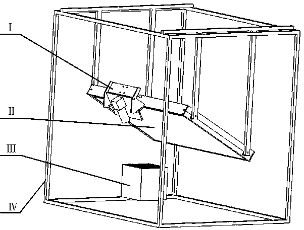
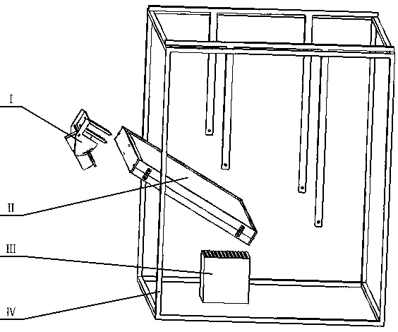
[0034] 1. See Figure 1 ~ Figure 6 , This highly reflective object surface light field refraction measurement system includes light field projection system II, light sensing system I, outer frame IV and object to be measured III; the light field sensing system I is supported by one of the camera angle adjustment plates 5 The screw connection is fixed on the upper cover plate 12 of a dual display in the light field projection system II; the light field projection system II is fixed on the outer frame IV through 4 connectors 6 screw connection; the object to be tested III is placed In the light field sensing system I, the area where the field of view of the camera 1 and the projection area of ​​the light field projection system II intersect.

Embodiment 2

[0035] The second embodiment: This embodiment is basically the same as the first embodiment, and the special features are as follows:

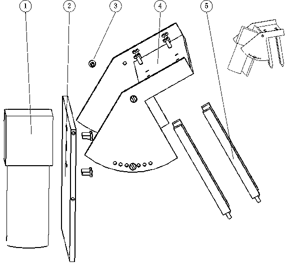
[0036] The light field sensing system I has an ordinary camera or light field camera 1 with a small aperture. The camera 1 is fixed on the camera support plate 2 by screws 3, and the camera support plate 2 is fixed on the camera by screws 3 On the angle adjustment plate 4, the camera angle adjustment plate 4 is fixed on the camera angle adjustment plate support 5 by screws 3; the light reflected from the surface of the object III is captured by the camera 1 to obtain the light field projected by the light field projection system II.

[0037] The light field projection system II: a front display 9 is inserted in a left card slot 7 of a front display and a right card slot 13 of a front display, the two card slots 7 and 13 are fixed on a dual display connection by screws 3 The cover 12 and a dual display are connected to the lower cover 11; a rear dis...

Embodiment 3

[0042] See Figure 7 ~ Figure 9 The system and method for measuring light field deflection on the surface of a highly reflective object is operated by the above system, and is characterized in that the operation steps are as follows: firstly, the projected light field is coded by the time-sharing method, the front display displays the modulated image, and the rear display displays a full white highlight. The camera shoots the pattern reflected by the object to be measured, and obtains the phase information of the surface of the object to be measured by phase recovery from the pattern shot by the camera. The rear display displays the modulated image, and the front display is all white highlighted. The camera shoots the pattern reflected by the object to be measured. The phase information of the surface of the object to be measured is obtained by phase recovery for the pattern shot by the camera; secondly, the phase information of the surface of the object to be measured obtained ...


PUM


Abstract

The invention relates to a high reflective object surface light field deflection technique measuring system and method, and is used for three-dimensional reconstruction of the high reflective object surface, the system adopts a light ray reflection principle to acquire normal information of the high reflective object surface and curved surface information, the system is projected by the light field, and the system is sensed through the light ray. The correspondence of an incident ray and a reflection ray are determined through a phase retrieval method, and 3D points on the to-be-detected object surface are calculated. According to the invention, compared with the common phase deflection technique, the system and the method does not have non-unique normal problem, and in light field camera mode, the system has higher response characteristics for object surface height variation, can get higher measuring precision and can fill the blank of domestic and overseas deflection technique measuring system based on light field.

Description

Technical field [0001] The invention is designed in the field of optical measurement, specifically a system and method for measuring light field deflection on the surface of a highly reflective object. Background technique [0002] Optical three-dimensional profile measurement technology has been widely used in aerospace, automobile manufacturing, reverse engineering, computer-aided design, computer-aided manufacturing and other fields due to its advantages of non-contact, high accuracy, and high speed. Structured light projection to obtain the three-dimensional surface shape of an object has the advantages of rapid full-field measurement and high measurement accuracy. It has been widely used in the three-dimensional measurement of diffuse reflection surfaces. Now in the manufacturing field, there are many measurement requirements for mirrors and near-mirror surfaces, such as the surface of optical components, mirrors, and polishing tools in the field of optical manufacturing. Ph...

Claims


Application Information

Patent Timeline
Patent Type & Authority Patents(China)
IPC IPC(8): G01B11/25
CPCG01B11/254
Inventor 张旭贾君慧李晨
Owner SHANGHAI UNIV
Why Eureka
Try Eureka