Antenna
An antenna and radome technology, which is applied to antennas, antenna arrays, antenna parts, etc., can solve the problems of increasing the cross-sectional area of the antenna, increasing the difficulty of processing, and product cost, so as to improve the electrical performance, increase the cost of raw materials, and improve the front and rear than the effect
- Summary
- Abstract
- Description
- Claims
- Application Information
AI Technical Summary
Problems solved by technology
Method used
Image

Examples
no. 1 example
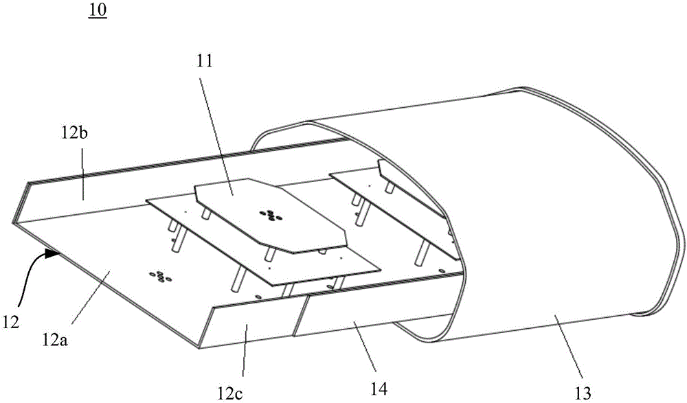
[0058] figure 1 is a three-dimensional structure diagram of the antenna of the first embodiment of the present invention. refer to figure 1 As shown, the antenna 10 in this embodiment includes an antenna element 11 , a reflector 12 , a radome 13 and a wave-absorbing material layer 14 .
[0059] The reflection plate 12 has a bottom plate 12a, a first side plate 12b, and a second side plate 12c. The first side plate 12b is opposite to the second side plate 12c. The reflecting plate 12 may also have a third side plate and a fourth side plate (not shown in the figure). The third side board is opposite to the fourth side board. The third side plate is adjacent to the first side plate 12b and the second side plate 12c, and the fourth side plate is also adjacent to the first side plate 12b and the second side plate 12c. As an example, the first side panel 12b and the second side panel 12c may be in the form of a regular rectangle, and the third side panel and the fourth side pan...
no. 2 example
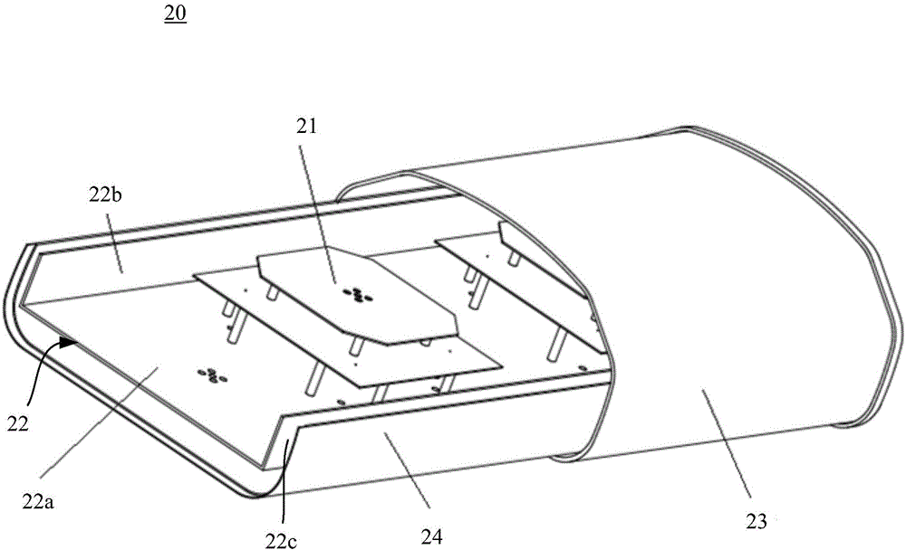
[0070] figure 2 is a three-dimensional structure diagram of the antenna of the second embodiment of the present invention. refer to figure 2 As shown, the antenna 20 in this embodiment includes an antenna vibrator 21 , a reflector 22 , a radome 23 and a wave-absorbing material layer 24 .
[0071] The reflection plate 22 has a bottom plate 22a, a first side plate 22b, and a second side plate 22c. The first side plate 22b is opposite to the second side plate 22c. The reflecting plate 22 may also have a third side plate and a fourth side plate (not shown in the figure). The third side board is opposite to the fourth side board. The third side plate is adjacent to the first side plate 22b and the second side plate 22c, and the fourth side plate is also adjacent to the first side plate 22b and the second side plate 22c. As an example, the first side panel 22b and the second side panel 22c may be in the shape of a regular rectangle, and the third side panel and the fourth sid...
no. 3 example
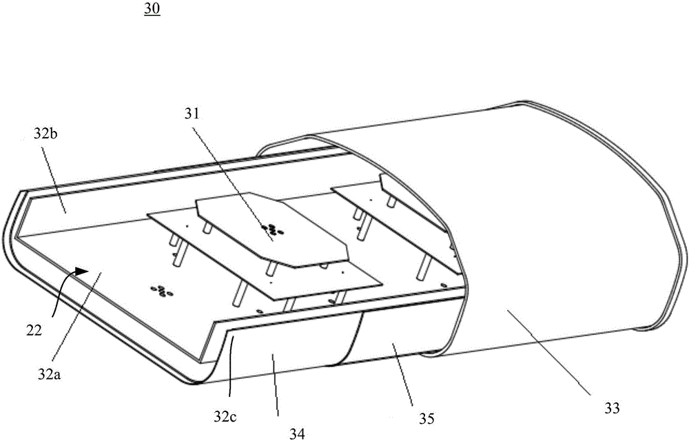
[0080] image 3 is a three-dimensional structure diagram of the antenna of the third embodiment of the present invention. refer to image 3 As shown, the antenna 30 in this embodiment includes an antenna vibrator 31 , a reflector 32 , a radome 33 and a wave-absorbing material layer 34 .
[0081] The reflection plate 32 has a bottom plate 32a, a first side plate 32b, and a second side plate 32c. The first side plate 32b is opposite to the second side plate 32c. The reflecting plate 32 may also have a third side plate and a fourth side plate (not shown in the figure). The third side board is opposite to the fourth side board. The third side plate is adjacent to the first side plate 32b and the second side plate 32c, and the fourth side plate is also adjacent to the first side plate 32b and the second side plate 32c. As an example, the first side panel 32b and the second side panel 32c may be in the form of a regular rectangle, and the third side panel and the fourth side pa...
PUM
| Property | Measurement | Unit |
|---|---|---|
| Thickness | aaaaa | aaaaa |
Abstract
Description
Claims
Application Information