
A Mirror Welding Method for Pipeline Leakage Plugging in Narrow Position

A welding method and pipeline technology, applied in welding equipment, tubular objects, arc welding equipment, etc., can solve the problems of not being able to see the back of the weld seam, inaccessibility of welders, arc scratches, etc., to solve the problems of weld root oxidation, Save time for overhaul and improve efficiency

Active Publication Date: 2017-11-17
DATANG HUAIBEI POWER PLANT
View PDF5 Cites 0 Cited by
  • Summary
  • Abstract
  • Description
  • Claims
  • Application Information

AI Technical Summary

Problems solved by technology

[0002] In recent years, in thermal power plants, due to the necessity of installation of many high-pressure units, ultra-high-pressure units and ultra-critical boiler units, there are many welding positions between tube rows that are difficult to see with the naked eye. During the welding process, there is a situation that cannot be seen in the position that cannot be seen, and the welding quality cannot be guaranteed. Forced welding will cause a series of defects such as pores, cracks, slag inclusions, undercuts, and arc scratches after welding, which is important for the safety of the boiler. Buried hidden dangers lead to unplanned outage accidents; pipes that require heat treatment, such as high-alloy pipes and T91, also create difficulties for heat treatment when welding defects occur; A lot of manpower, material and financial resources; the small mirror is adsorbed on another position of the whole row of pipes with a magnet, and the welding is performed through the back of the mirror to the extent that it can be seen by the naked eye, which not only saves maintenance time but also saves welding material costs. After mirror welding, the weld seam is smooth and smooth without trachoma. For example, in the repair of two boilers in Pengcheng Power Plant, the middle and high-grade re-pipe T91 welding consumable defect treatment, because the distance between the two rows of pipes is too close, the welding personnel cannot enter between the rows. Welding, and the back of the weld cannot be seen from the front

Method used


Image

  • A Mirror Welding Method for Pipeline Leakage Plugging in Narrow Position

Examples


Embodiment Construction

[0027] In order to make the technical problems, technical solutions and advantages to be solved by the present invention clearer, the following will describe in detail with reference to the drawings and specific embodiments.

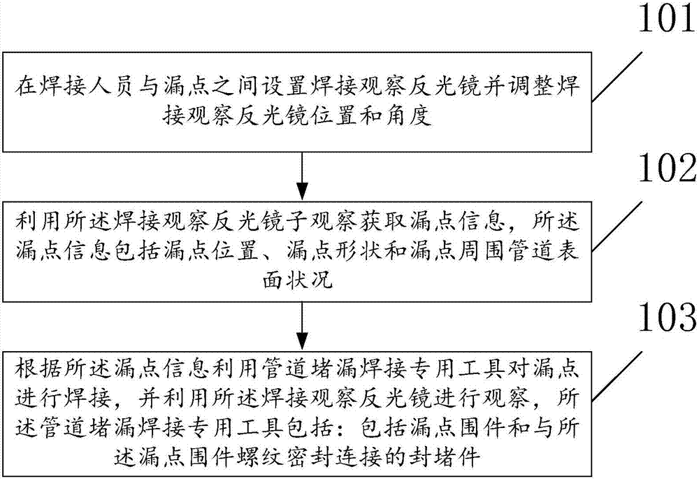
[0028] like figure 1 As shown, a mirror welding method for pipeline leakage plugging in a narrow position according to an embodiment of the present invention, the mirror welding method for pipeline leakage plugging in a narrow position comprises:

[0029] Step 101: setting up a welding observation mirror between the welder and the leakage point and adjusting the position and angle of the welding observation mirror;

[0030] Step 102: Use the welding observation mirror to observe and obtain leak point information, and the leak point information includes the leak point location, leak point shape, and pipeline surface conditions around the leak point;

[0031] Step 103: According to the leak point information, use the special tool for pipeline leak pluggin...


PUM


Abstract

The invention provides a narrow position pipe leakage blocking mirror surface welding method. The method comprises the following steps: a welding observation reflecting mirror is arranged between a welding person and a leakage point, and the position and the angle of the welding observation reflecting mirror are adjusted; and the leakage point is welded by using a special pipe leakage blocking welding tool according to the leakage point information. The narrow position pipe leakage blocking mirror surface welding method is convenient for leakage blocking welding of a pipe in a narrow position under the condition of not influencing the operation of the pipe, preferably solves the root oxidation problem of a welding line, guarantees the quality, improves the efficiency, reduces troubles for maintainers, prevents the rework defect due to continuous cutting of a peripheral pipe bundle, and saves the overhauling time.

Description

technical field [0001] The invention relates to the field of welding technology, in particular to a mirror welding method for leak plugging of pipelines in narrow positions. Background technique [0002] In recent years, in thermal power plants, due to the necessity of installation of many high-pressure units, ultra-high-pressure units and ultra-critical boiler units, there are many welding positions between tube rows that are difficult to see with the naked eye. During the welding process, there is a situation that cannot be seen in the position that cannot be seen, and the welding quality cannot be guaranteed. Forced welding will cause a series of defects such as pores, cracks, slag inclusions, undercuts, and arc scratches after welding, which is important for the safety of the boiler. Buried hidden dangers lead to unplanned outage accidents; pipes that require heat treatment, such as high-alloy pipes and T91, also create difficulties for heat treatment when welding defect...

Claims


Application Information

Patent Timeline
Patent Type & Authority Patents(China)
IPC IPC(8): B23K9/16B23K9/235B23K101/06
CPCB23K9/16B23K9/235B23K2101/06
Inventor 张浩
Owner DATANG HUAIBEI POWER PLANT
Learn More