Plastic optical fiber laser-welding technique and application thereof

A plastic optical fiber and laser welding technology, applied in laser welding equipment, welding equipment, manufacturing tools, etc., can solve problems such as difficult quality assurance, low production efficiency, and high labor intensity, and achieve small vibration stress and thermal stress and slow down aging Speed, less resin degradation effect

Inactive Publication Date: 2016-08-03
CHANGZHOU HUASHENG FUTAO PHOTOELECTRIC SCI ANDTECH CO LTD
View PDF3 Cites 2 Cited by
  • Summary
  • Abstract
  • Description
  • Claims
  • Application Information

AI Technical Summary

Problems solved by technology

The traditional thermoplastic connection method has many disadvantages: using screws, snap rings and other mechanical connections, the strength is not easy to meet the requirements and the quality of the connection surface cannot be required; the adhesive bonding method needs to be roughened and glued on the su

Method used


Image

  • Plastic optical fiber laser-welding technique and application thereof
  • Plastic optical fiber laser-welding technique and application thereof

Examples


Embodiment 1

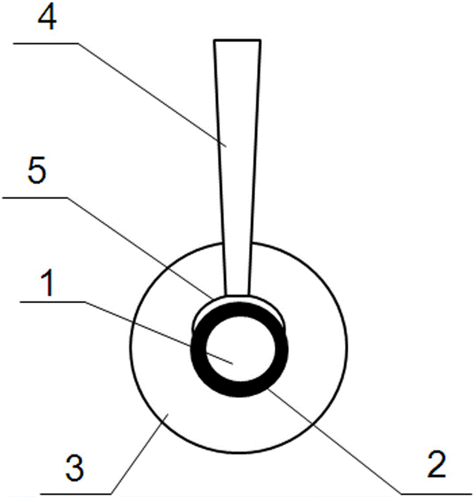
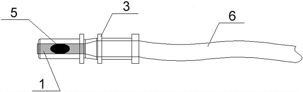
[0025] Such as figure 1 and 2 Shown, the plastic optical fiber laser welding process of the present invention is:

[0026] 1. Install the plastic ferrule (3) on the inner sheath (2) outside the plastic optical fiber core (1) at one end of the plastic optical fiber (6) to be welded;

[0027] 2. The semiconductor laser emits near-infrared laser light (4) passing through the plastic ferrule (3);

[0028] 3. The laser light (4) is absorbed by the inner sheath (2) of the plastic optical fiber (6);

[0029] 4. The inner sheath (2) converts light energy into heat energy and melts the contact surface of the inner sheath (2);

[0030] 5. Heat energy is simultaneously transmitted to the inner surface of the plastic ferrule (3) that transmits the near-infrared laser, forming a melting zone, and the melting zone produces intermolecular mixing;

[0031] 6. A welding seam is formed at the welding surface (5) during the rapid cooling process.

Embodiment 2

[0033] Such as figure 1 and 2 As shown, the wavelength of the near-infrared laser (4) used in the present invention is 940nm.

[0034] The technical parameters of the laser welding process of the present invention are: energy density ED=0.364J / mm 2 , Welding power P=40W, the power is 40W, the beam transmission mode is optical fiber, and the welding speed is 40mm / s.

[0035] The above plastic optical fiber inner sheath (2) is made of PA12 plastic containing carbon black, and the plastic ferrule (3) is made of transparent PA12 plastic.

[0036] This process uses a semiconductor laser welding process to weld the plastic ferrule to the inner sheath of the plastic optical fiber. Laser welding can produce precise, strong and sealed welds, and there is less resin degradation, less debris, and no pollution due to the non-contact nature of the laser. Another advantage is that laser welding produces less vibration than other joining methods. The stress and thermal stress are small, ...

Embodiment 3

[0038] Such as figure 1 and 2 As shown, the wavelength of the near-infrared laser (4) used in the present invention is 810nm.

[0039] The technical parameters of the laser welding process of the present invention are: energy density ED=0.351J / mm 2 , welding power P=20W, beam transmission mode is optical fiber, welding speed is 5mm / s.


PUM

PropertyMeasurementUnit
Wavelengthaaaaaaaaaa

Abstract

The invention provides a plastic optical fiber laser-welding technique. The plastic optical fiber laser-welding technique is characterized in that a plastic ferrule is welded to an inner jacket of a plastic optical fiber through a semiconductor laser-welding technique. Through laser welding, precise, firm and sealed weld joints can be formed, the resin degradation quantity is small, and few chips are generated; through the non-contact property of laser, no pollution is generated; and the vibrating stress and thermal stress generated by laser welding are smaller than the vibrating stress and thermal stress generated by other connection ways, and the aging speed of the interior of the optical fiber can be effectively decreased.

Description

technical field [0001] The invention relates to the production technology of wire harnesses for vehicles, in particular to a plastic optical fiber laser welding process and its application. Background technique [0002] In the mass production of plastic optical fiber for vehicles, it is necessary to weld the plastic ferrule to the inner sheath of the plastic optical fiber, and then assemble it into the connector. The traditional thermoplastic connection method has many disadvantages: using screws, snap rings and other mechanical connections, the strength is not easy to meet the requirements and the quality of the connection surface cannot be required; the adhesive bonding method needs to be roughened and glued on the surface , Bonding, curing, ironing, trimming and other processes are all manually operated, with high labor intensity, many processes, low production efficiency, and difficult quality assurance. Moreover, the volatile components of the adhesive pollute the envir...

Claims


Application Information

Patent Timeline
IPC IPC(8): B23K26/24B23K26/324B23K26/18
CPCB23K26/24B23K26/18B23K26/324
Inventor 金小平陆武立张生富
Owner CHANGZHOU HUASHENG FUTAO PHOTOELECTRIC SCI ANDTECH CO LTD
Why Eureka
Try Eureka