

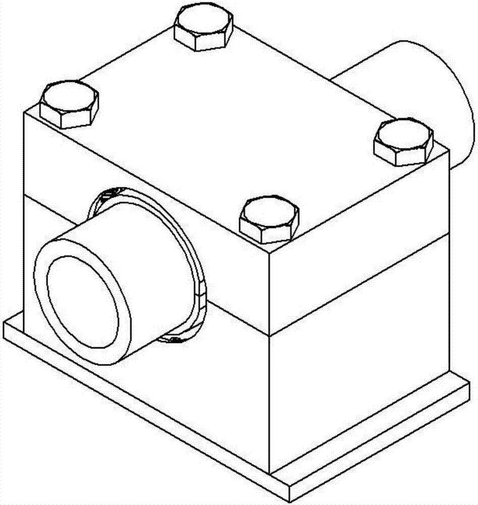
A two-dimensional magnetorheological damping tube clamp
A magnetorheological and vibration-damping tube technology, applied in the direction of shock absorbers, shock absorbers, pipeline supports, etc., can solve the problems of consuming pipeline vibration energy, weakening fluid pressure pulsation, weakening vibration transmission, etc., to reduce pressure pulsation. , the effect of weakening the propagation and suppressing the fluid-structure interaction
- Summary
- Abstract
- Description
- Claims
- Application Information
AI Technical Summary
Problems solved by technology
Method used
Image

Examples
Embodiment Construction
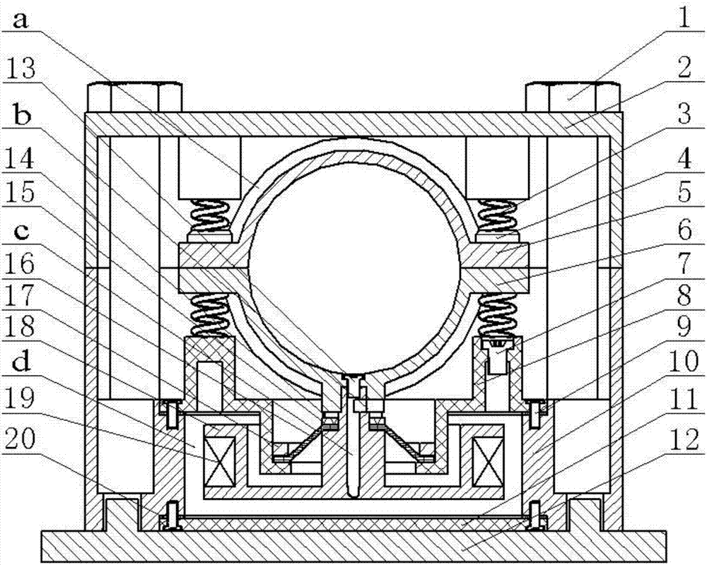
[0011] The technical scheme adopted in the present invention:
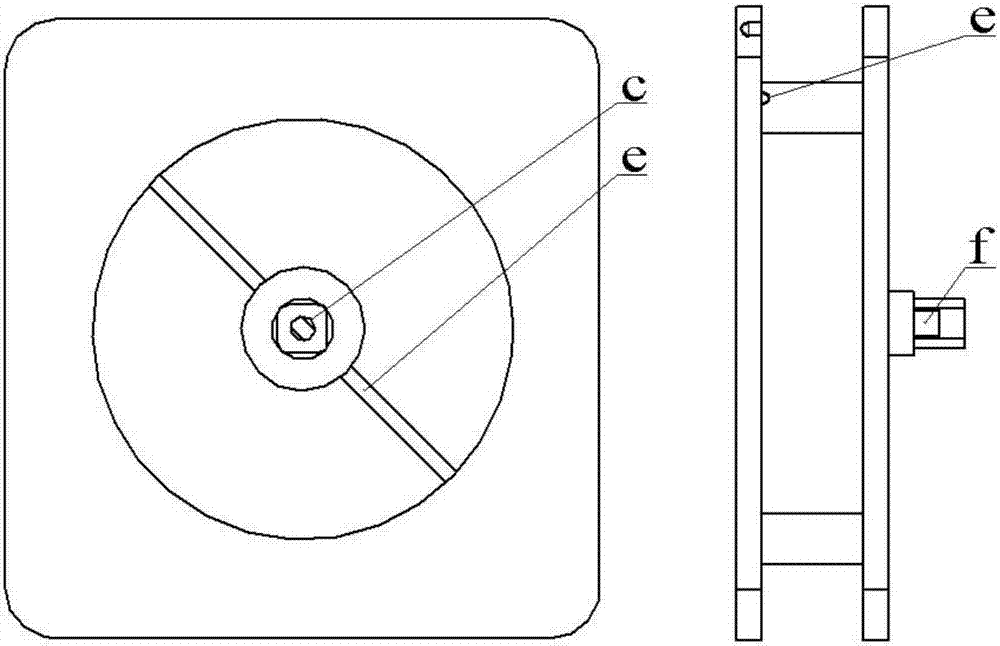
[0012] A two-dimensional magnetorheological damping tube clamp, mainly including magnetorheological fluid, base 10, upper cover 8, lower cover 11, leather cup 16, piston 18, electromagnetic coil 19, upper inner tube clamp 5, lower side Inner tube clip 6, spring 3; Piston 18 is installed in the cylinder body surrounded by lower cover 11, base 10, upper cover 8 and leather cup 16, and base 10 and piston 18 are made of magnetic material No. 45 steel; The cover 8 and the lower cover 11 are made of non-magnetic aluminum alloy, fixed to the base 10 by the base screw 9, and sealed with a gasket 20; the gap d between the piston 18 and the cylinder is filled with magnetorheological fluid, and the piston rod wears Pass the leather cup 16, the piston gland 15 and the piston nut 14 and connect with the lower inner pipe clamp 6; the piston nut 14 cooperates with the thread on the piston rod, and the leather cup 16 is fixed on ...
PUM
 Abstract
Description
Claims
Application Information