Digital Switching Converter Protection Circuit

A protection circuit and digital switch technology, applied in emergency protection circuit devices, automatic disconnection emergency protection devices, circuit devices, etc. Easy to debug and enhance the effect of self-recovery ability

Inactive Publication Date: 2018-09-18
WUHAN UNIV OF TECH
View PDF5 Cites 0 Cited by
  • Summary
  • Abstract
  • Description
  • Claims
  • Application Information

AI Technical Summary

Problems solved by technology

[0004] The technical problem to be solved by the present invention is to provide a digital switching converter protection circuit to enhance its ability to interact with digital controller information, and at the same time solve the problem that the digital switching converter lacks the ability to automatically restart under a specific fault

Method used


Image

  • Digital Switching Converter Protection Circuit
  • Digital Switching Converter Protection Circuit
  • Digital Switching Converter Protection Circuit

Examples


Embodiment 1

[0038] Embodiment 1. Digital switching converter protection circuit

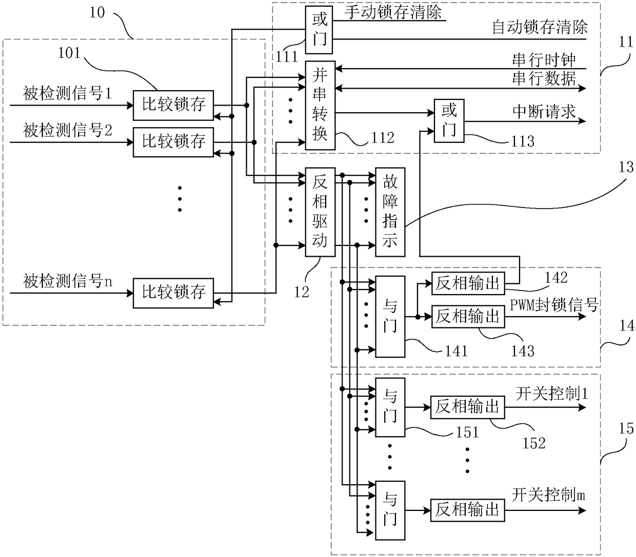
[0039] The structure of the digital switching converter protection circuit is as follows figure 1 As shown, it consists of a fault signal latch circuit 10, a fault information transmission circuit 11, an inverting drive circuit 12, a fault indication circuit 13, a pulse blocking signal circuit 14 and a switch signal circuit 15. The input terminal of the fault signal latch circuit 10 receives the detected signal, and its output terminal is respectively connected to the input terminals of the fault information transmission circuit 11 and the inverter circuit 12 . The output terminals of the anti-phase driving circuit 12 are respectively connected with the fault indication circuit 13 , the pulse blocking signal circuit 14 and the switch signal circuit 15 .

[0040]The fault signal latch circuit 10 includes n comparison latch circuits 101, which are used to perform comparison operations on n-way detected signal...

Embodiment 2

[0045] Embodiment 2. Application of digital switching converter protection circuit

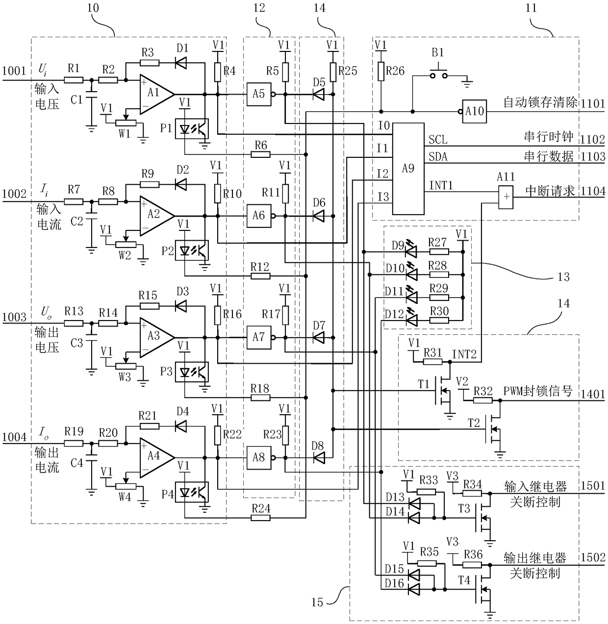
[0046] The digital switching converter protection circuit provided in Embodiment 2 is used for overvoltage and overcurrent protection of the digital switching converter.

[0047] figure 2 Middle: The fault signal latch circuit 10 includes four comparison latch circuits 101 , which is an example of n=4. Wherein the first comparison latch circuit 101 is composed of filter capacitor C1, comparator A1, potentiometer W1, diode D1 and photoelectric isolator P1; the other three comparison latch circuits have the same structure as the first comparison latch circuit, Respectively composed of filter capacitor C2 to filter capacitor C4, comparator A2 to comparator A4, potentiometer W2 to potentiometer W4, diode D2 to diode D4, and photoelectric isolator P2 to photoelectric isolator P4; the filter capacitor and the corresponding The resistor forms a resistance-capacitance filter circuit, the comparator...

Embodiment 3

[0064] Embodiment 3. Application of digital switching converter protection circuit

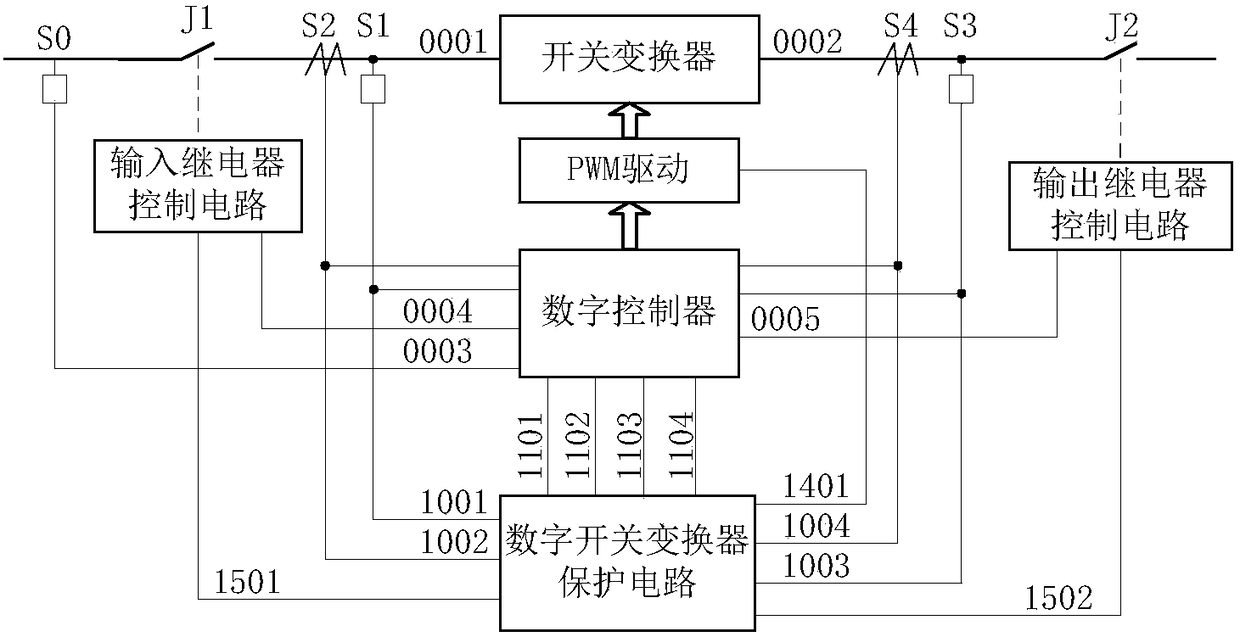
[0065] This protection circuit is used for fault protection of digital switching converters, and its structure is as follows image 3 shown.

[0066] An input-side relay and an output-side relay are respectively arranged in the main circuit of the switching converter, and the protection circuit of the digital switching converter detects an input voltage and an input current at the output terminals of the input-side relay respectively, and at the input of the output-side relay The terminals detect the output voltage and output current respectively. The digital controller detects the input voltage at the input terminal of the input side relay. The fault information transmission circuit of the protection circuit of the digital switching converter is connected with the digital controller; the PWM blocking signal in the pulse blocking signal circuit of the protection circuit of the digital switch...


PUM


Abstract

The invention relates to a digital switching converter protection circuit. The digital switching converter protection circuit is composed of a fault signal latch circuit (10), a fault information transmission circuit (11), a reversed phase driving circuit (12), a fault indication circuit (13), a pulse blocking signal circuit (14) and a switching signal circuit (15); the input end of the fault signal latch circuit receives detected signals, and the output ends of the fault signal latch circuit are connected with the input ends of the information transmission circuit (11) and the reversed phase driving circuit (12); and the output ends of the reversed phase driving circuit (12) are connected with the fault indication circuit (13), the pulse blocking signal circuit (14) and the switching signal circuit (15) respectively. With the digital switching converter protection circuit of the invention adopted, transient overvoltage fault protection can be restarted automatically, and self recovery ability is enhanced, the reliability of a digital switching converter system is improved. The protection circuit is in a modular protection circuit, and therefore, expansion can be facilitated, and the design, production and manufacture of digital switching converter products can be benefitted.

Description

technical field [0001] The invention relates to the field of switching converters, in particular to a protection circuit for digitally controlled switching converters. Background technique [0002] With the development of new energy technology, the application of power electronic switching converters in the field of new energy is becoming more and more extensive. The control and protection of traditional switching converters are mostly realized by using special switch control chips and analog detection circuits. At present, digital control technology is gradually popularized in the control application of switching converters. Digital controllers can not only realize the switching signals of traditional analog chips Generation and closed-loop control can also intelligently protect the converter circuit effectively. In terms of circuit protection of digital switching converters, fully combining the rapidity of analog circuits and the intelligent characteristics of digital con...

Claims


Application Information

Patent Timeline
Patent Type & Authority Patents(China)
IPC IPC(8): H02H7/10H02H3/06
CPCH02H3/06H02H7/10
Inventor 夏泽中王振吴泽昊
Owner WUHAN UNIV OF TECH
Why Eureka
Try Eureka