
Stainless steel foil and method for manufacturing same

A stainless steel foil and stainless steel technology, applied in the field of stainless steel foil, can solve the problems of not being able to apply the battery case, etc., and achieve the effects of good electrolyte resistance, good stamping processability, and high plate thickness accuracy

Active Publication Date: 2016-08-03
NIPPON STEEL CHEMICALL &MATERIAL CO LTD
View PDF8 Cites 5 Cited by
  • Summary
  • Abstract
  • Description
  • Claims
  • Application Information

AI Technical Summary

Problems solved by technology

In the case of battery casings, if it is not an ultra-thin stainless steel foil with a thickness of 60 μm or less, it cannot be applied to battery casings required by current electronic equipment

Method used


Image

  • Stainless steel foil and method for manufacturing same
  • Stainless steel foil and method for manufacturing same

Examples


Embodiment

[0109] [Example]

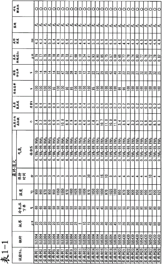
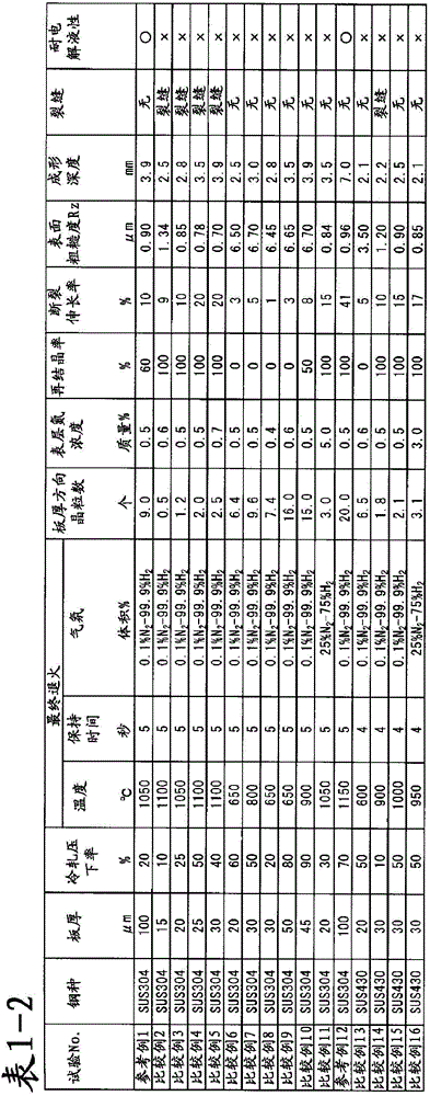
[0110] As an example of the ultra-thin stainless steel foil according to the present invention, commercially available SUS304 (austenitic stainless steel) and SUS430 (ferritic stainless steel) were rolled by a foil rolling mill under the rolling conditions described in Table 1. An ultra-thin stainless steel foil having the thickness described in Table 1 was manufactured.

[0111] Here, the cold rolling reduction represents the reduction in the foil rolling process immediately before the final annealing, the final annealing temperature represents the temperature in the final annealing process performed after the rolling process is completed, and the holding time represents the temperature at the final annealing temperature. time to keep the stainless steel foil under.

[0112] The annealing atmosphere is set as 0.1 vol% nitrogen-99.9 vol% hydrogen mixed gas or 25 vol% nitrogen-75 vol% hydrogen mixed gas.

[0113] The recrystallization rate is observed by mirr...

reference example 1

[0123] Reference examples 1 and 12 are examples of stainless steel foils with a plate thickness of 100 μm. In Reference Example 1, although the annealing temperature was relatively high, the sheet thickness was thick and recrystallization did not proceed. However, since the plate thickness is thick, the number of crystal grains in the cross section is 9, and the elongation at break and the forming depth are secured to some extent. Reference Example 11 is an example in which both the elongation at break and the depth of forming are very good because the recrystallization rate is 100%. Thus, it can be seen that, when the plate thickness is thick like the conventional stainless steel foil, the elongation at break becomes good and the plastic deformability is ensured, so that the subject of the present invention is not conspicuous.

[0124] In addition, Examples 20-29 and Comparative Examples 13-16 are the examples which used SUS430. In comparing SUS304 and SUS430, it was confir...


PUM


Abstract

The present invention addresses the problem of securing high thickness accuracy even for ultra-thin stainless steel foil having a thickness of 60 mum or less while also securing plastic deformability and breaking elongation, that is, securing excellent press workability (deep drawability). The present invention solves the above problem by providing an ultra-thin stainless steel foil, which has 3 or more crystal grains in the thickness direction, and in which the recrystallization rate is between 90% and 100% inclusive, and the nitrogen concentration at the surface is 1.0 mass% or less. Thus, with this method for manufacturing an ultra-thin stainless steel foil having a thickness of 5 to 60 mum by rolling a stainless steel sheet and subsequently performing final annealing, it is possible to manufacture an ultra-thin stainless steel foil in which the rolling reduction from rolling immediately prior to the final annealing is 30% or more, the post-rolling final annealing temperature is 950 DEG C to 1050 DEG C in the case of austenitic stainless steel and 850 DEG C to 950 DEG C in the case of ferritic stainless steel, and the nitrogen content of the atmosphere gas during final annealing is 0.1 vol% or less.

Description

technical field [0001] The present invention relates to a stainless steel plate (stainless steel foil) having a thickness of 60 μm or less. In particular, it relates to a stainless steel foil having workability and corrosion resistance among extremely thin stainless steel plates. Background technique [0002] With the miniaturization and weight reduction of electronic equipment, the portability and mobility of electronic equipment are progressing, and batteries such as lithium ion batteries mounted in many electronic equipment are required to be miniaturized and lightweight. In particular, the miniaturization and weight reduction of batteries required for electronic devices such as smartphones require state-of-the-art specifications. [0003] Currently, battery cases for lithium-ion batteries for smartphones use can-shaped aluminum sheets and aluminum foil laminated with resin films. In particular, an aluminum foil laminated with a resin film is often used for the purpose ...

Claims


Application Information

Patent Timeline
IPC IPC(8): C22C38/00B32B15/08C21D9/46H01M2/02H01M50/119H01M50/121H01M50/124H01M50/129H01M50/131H01M50/133
CPCC21D9/46C21D6/002C21D8/0236C21D8/0257C21D8/0273B32B15/18B32B2457/10C22C38/40C21D1/74C21D8/005C21D9/0068C21D2211/001C21D2211/005Y02E60/10H01M50/133H01M50/121H01M50/129H01M50/124H01M50/131H01M50/119C22C38/18H01M50/102
Inventor 海野裕人寺岛晋一稻熊彻能势幸一藤本直树佐胁直哉长崎修司
Owner NIPPON STEEL CHEMICALL &MATERIAL CO LTD
Learn More