High-heeled shoes with replaceable heels

A replaceable, high-heeled shoe technology, applied in the direction of footwear, heels, heel pads, etc., can solve the problems of complicated processing technology, inelasticity, cumbersome operation, etc., and achieve high material utilization and strength performance, and disperse materials Loss and strength loss, the effect of simple replacement procedures

Active Publication Date: 2016-08-10
HANGZHOU JIUBA HONGTU TECH CO LTD
View PDF9 Cites 11 Cited by
  • Summary
  • Abstract
  • Description
  • Claims
  • Application Information

AI Technical Summary

Problems solved by technology

But also there is following defect in this utility model in use: 1), locking mechanism comprises trigger switch, fixing sleeve, elastic locking plate, movable shaft (as attached Figure 4 As shown), the integrated design structure is fixed on the receiving structure layer fixedly connected with the sole, which is equivalent to installing all parts of the locking mechanism of the integrated structure on the sole. On the one hand, the sole must be provided with a large area of ​​space to accommodate the locking mechanism. It will inevitably affect the strength of the sole; on the other hand, due to the overall structural design, when the parts of the locking mechanism are damaged and need to be replaced, the locking mechanism must be taken out as a whole. Not only the replacement steps are troublesome, but also multiple operations will affect the locking mechanism. The matching strength of the sole and the service life of the shoes are easy to damage the sole. At the same time, the locking mechanism must be disassembled when replacing the parts, which also affects the matching strength between the parts. In addition, if some parts cannot be disassembled and replaced, it is necessary to Requires replacement of the entire locking mechanism, increasing repair costs
2) The trigger switch is set at the position of the sole, so the built-in button design of the sole is cumbersome to operate. When replacing the heel, it is necessary to take off the shoe, especially in public places, which is very inconvenient and seriously affects the image of women; the trigger switch on the sole will This results in a concave-convex feeling on the sole, which affects the comfort of women wearing high-heeled shoes at the slightest level, and at worst causes the skin on the sole of the foot to be damaged; 3) The fixed sleeve is placed outside the elastic cleat, which not only complicates the processing technology, but also increases the accommodation space of the sole , the volume of the bottom surface of the corresponding sole is reduced, and the strength is also affected
4) In order to realize the technical solution, the elastic cleat must protrude from the supporting structure layer of the sole and fasten with the concave part of the sole, and the hollow cavity of the sole communicates with the guide chute. If you wear such replaceable high-heeled shoes on rainy days, It is easy to cause water to enter the sole, which seriously affects the wearing comfort and the service life of high-heeled shoes; 5), the heel bump matches the guide chute of the sole, and there is an obvious "several" shape at the matching place behind the heel Seams, which seriously affect the appearance of high heels
The technical solution of this utility model still has the following technical problems: 1), in this utility model, the buckle is arranged in the draw-in groove with the mode that runs through the sole, and by pressing the mode of the sole buckle, the heel and the sole can be realized. Disassemble the connection, the lock of the locking mechanism and the button for pressing the lock are integrally installed on the sole of the shoe as in the above patent. If it is replaced, the locking mechanism must be taken out as a whole. Not only the replacement steps are troublesome, but also pulling in and out will affect the connection between the locking mechanism and the sole. Cooperating with the strength and the service life of the shoes, it is easy to damage the soles, increasing the risk and cost of maintenance; 2), the simple buckle and the sole button connected to the buckle need to be pressed on the sole button with a relatively large force. To ensure that the buckle is detached from the sole, women tend to have less strength, and sometimes even cannot replace the heel because the buckle cannot be pressed; the buckle structure is thin and has no elasticity, and the force required is too large. The phenomenon that the lock button is stuck on the sole of the shoe and cannot be ejected will also cause the phenomenon that the lock cannot be stuck on the heel. In this way, it is not only difficult to use, but also affects the quality. Changing the heel has become a shoe repair and a shoe change. The high-heeled shoes designed in this way will not become the final choice of women; 3), the lock button is set at the position of the sole, so the built-in button design of the sole is cumbersome to operate, and when replacing the heel, it is necessary to take off the shoe, especially in public places. It is inconvenient and seriously affects the image of women; in addition, the buttons on the sole will cause the sole to have a concave-convex feeling, which will affect the comfort of women wearing high-heeled shoes at the slightest level, and at the worst will cause the skin on the sole of the foot to be injured; 4), the lock buckle protrudes from the sole and the sole The lock groove is fastened, and the sole is connected with the card groove. If you wear such interchangeable high-heeled shoes on rainy days, it is easy to cause water to enter the sole, which will seriously affect the wearing comfort and the service life of the high-heeled shoes; 5), the heel buckle and the sole There are obvious "several"-shaped seams at the matching place behind the heel, which seriously affects the appearance of the high-heeled shoes
The defects of this utility model are as follows: 1), the lock is fixed to the insole of the shoe on the substantially entire surface of the heel seat and the waist of the shoe, and the lock is still integrated in the design structure and installed on the sole. On the one hand, the sole must be provided with a large area of ​​space to It accommodates the locking mechanism, which will inevitably affect the strength of the sole; on the other hand, due to the overall structural design, when the parts of the locking mechanism are damaged and need to be replaced, the locking mechanism must be taken out as a whole. Not only the replacement steps are troublesome, but also multiple operations It will affect the matching strength between the locking mechanism and the sole and the service life of the shoes, and it is easy to damage the sole. At the same time, the locking mechanism must be disassembled when replacing parts, which also affects the matching strength between parts. In addition, if some parts cannot By disassembling and replacing, it is necessary to replace the entire locking mechanism, increasing maintenance costs
2) The lock mechanism has seams on the surface of the shoe body, which affects the aesthetics of the high-heeled shoe body; 3), from the content disclosed in the document, it can be deduced that the unlock button may be set on the sole, so the built-in button design operation of the sole It is cumbersome. When replacing the heels, it is necessary to take off the shoes, especially in public places, which is very inconvenient and seriously affects the image of women; 4), the lock is fixed to the inner sole of the shoe on the basic entire surface of the heel seat and the waist of the shoe. The lock must be because the heel is buckled, so the inside of the sole needs to be connected with the outside. If it is raining, wear This kind of replaceable high-heeled shoes can easily cause water to enter the sole, which seriously affects the wearing comfort and the service life of the high-heeled shoes.
[0006] Therefore, in view of the above-mentioned defects existing in the current prior art, it is necessary to carry out research to provide a solution to solve the defects existing in the prior art and avoid the problem that women need to carry more high-heeled shoes in response to different occasions.

Method used


Image

  • High-heeled shoes with replaceable heels
  • High-heeled shoes with replaceable heels
  • High-heeled shoes with replaceable heels

Examples


Embodiment 1

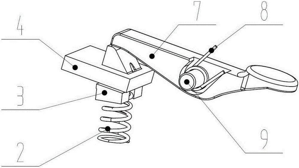
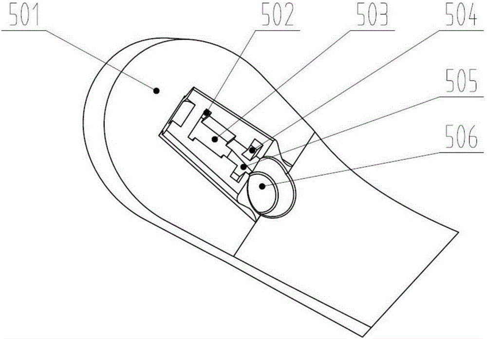
[0039] Example 1: figure 1 It is a schematic diagram of the overall structure of Embodiment 1 of the present invention, a high-heeled shoe with a replaceable heel, including a sole 5 and a heel 1, and a heel-off docking device is arranged between the sole 5 and the heel 1 of the high-heeled shoe, and the heel-off docking device includes The clamping structure is fixed on the heel 1, the elastic ejector pin that engages the shoe sole 5, and the pressure bar structure that is fixed on the sole 5 and drives the elastic ejector pin to separate from the sole 5. Groove and the block that mortises and mortises with the groove, the block is set on the sole 5, the block is formed by the first groove 501 on the sole 5, the bottom surface of the first groove 501 is parallel to the upper plane of the heel 1, elastic The push rod is located in the slot of the heel 1, figure 2 It is a schematic diagram of the structure of the pressure rod structure and the elastic ejector rod in Embodime...

Embodiment 2

[0042] Embodiment 2: In this embodiment, the button 10 and the pressing rod 7 are integrally formed, the soft rubber pad on the button 10 is cemented with the material of the sole 5, and the soft rubber pad and the pressing rod 7 are fixed together, which is convenient for assembly. The fixed shaft 9 is two semi-axles protruding from the side of the pressure bar 7 and integrally formed with the pressure bar 7. They are fixed in the fourth groove 504 through interference fit, and the second spring 8 is not provided, because the shoe sole 5 and the shoe In the process of combining with 1, the movable push rod 3 of the elastic push rod will withstand the end face of the pressure rod 7 to make it reset, the shape of the button 10 is disc-like or polygonal, and the shape of the sixth groove 506 is circular or polygonal. The bottom surface of the groove of the fixed wear-resistant metal sheet 6 forms an included angle of 15 degrees with the upper plane of the heel 1, and the middle p...

Embodiment 3

[0043] Example 3: Figure 5 It is a schematic diagram of the sole structure of Embodiment 3 of the present invention. In this embodiment, the fixed shaft 9 is a shaft that passes through the through hole of the pressure rod 7 and forms an angle of 90 degrees with the side of the pressure rod 7, and is fixed on the sole 5 through interference fit. In the slot hole 12 or the through hole, the material of the heel 1 and the sole 5 is 304 stainless steel, and the fixed piece 4, the wear-resistant metal sheet 6 and the soft rubber pad are not provided. The function of the movable ejector rod 3 is not affected if the soft rubber pad is not provided. It is directly buckled on the flange of the second groove 502. The first spring 2 is an air spring. The reinforcing rod forms an angle of 65 degrees with the upper plane of the heel 1. The middle part of the heel 1 is provided with a reinforcing rod. The upper plane of the heel 1 forms an angle of 70 degrees, the joint surface of the mov...


PUM


Abstract

The invention discloses a pair of high-heeled shoes with replaceable heels. Each high-heeled shoe comprises a shoe sole and a heel, wherein a heel butt joint device is arranged between the shoe sole and the heel; the heel butt joint device comprises a clamping structure, an elastic ejection rod which is fixed on the heel and is used for clamping the shoe sole, and a pressing rod structure which is fixed on the shoe sole and drives the elastic ejection rod to be released from the shoe sole. The pressing rod structure and the elastic ejection rod are separately designed, and parts are convenient to replace; space utilization ratios of the shoe sole and the heel are proper, the loss cost of the parts is reduced and pressing saves more power; a press button is located on the surface of a shoe body and the pressing is convenient; the high-heeled shoe is simple and convenient to replace; the press button is arranged on the shoe sole and is hidden at an engaged part of the heel and the shoe sole; the appearance line of the high-heeled shoe is smoother and more beautiful, the wearing comfort is improved and the service life of the high-heeled shoe is prolonged.

Description

technical field [0001] The invention belongs to the technical field of high-heeled shoes, and in particular relates to a high-heeled shoe with a replaceable heel, good comfort and beautiful appearance. Background technique [0002] High heels are almost a must-have in women's shoe cabinets these days. To attend different occasions, you need to wear high-heeled shoes with different heels or different styles. High-heeled shoes with different heels are suitable for women with different styles. To increase the burden of life, if you can overcome the fixed heel design and change the heel shape that women like at will, so as to cope with various occasions, these are the ideal high heels that women who love beauty dream of. [0003] In order to solve the above problems, Chinese patent (Patent No. 201520780664.4) discloses a high-heeled shoe with a trigger switch. By setting a locking mechanism with a trigger switch between the high-heeled shoe body and the heel, the locking mechan...

Claims


Application Information

Patent Timeline
Patent Type & Authority Applications(China)
IPC IPC(8): A43B21/42A43B7/38
CPCA43B7/38A43B21/42
Inventor 李相清马丽许慧杰
Owner HANGZHOU JIUBA HONGTU TECH CO LTD
Why Eureka
Try Eureka