
Automatic pipe cutting machine

A pipe cutting machine and automatic technology, which is applied to pipe shearing devices, shearing devices, accessories of shearing machines, etc., can solve the problems of increasing production costs and other problems, and achieve convenient cutting length adjustment, wide application range and low cost. Effect

Pending Publication Date: 2016-08-10
黄明桂
View PDF0 Cites 28 Cited by
  • Summary
  • Abstract
  • Description
  • Claims
  • Application Information

AI Technical Summary

Problems solved by technology

In this way, there is no doubt that the input that increases the production cost

Method used


Image

  • Automatic pipe cutting machine
  • Automatic pipe cutting machine
  • Automatic pipe cutting machine

Examples


Embodiment

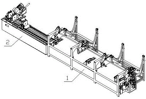
[0058] Embodiment: a kind of automatic pipe cutting machine, as figure 1 As shown, it includes a feeding mechanism 1, a pipe cutting mechanism 2 and a control system. The feeding mechanism 1 is arranged at the rear of the pipe cutting mechanism 2, and supplies the pipe material to be cut for the pipe cutting mechanism 2.

[0059] In this embodiment, the automatic pipe cutting machine also includes a blanking mechanism (not shown in the figure), which is arranged in front of the pipe cutting mechanism 2, and the control system controls the blanking mechanism, the pipe cutting mechanism 2 and the feeding mechanism. Collaborative work of Agency 1.

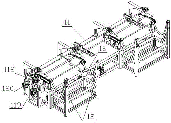
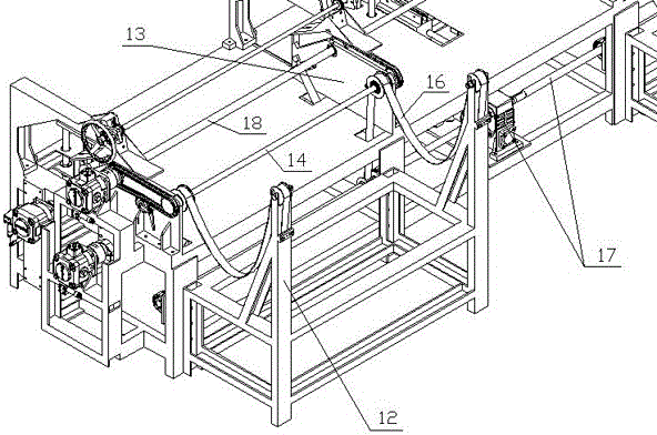
[0060] Such as Figure 2~5 As shown, the feeding mechanism 1 includes a frame 11, a plurality of support columns 12 are arranged on the right side of the frame 11, and a plurality of mechanism mounting plates 13 are arranged in parallel on the left side of the frame 11. Mechanism mounting plate 13 is provided with rotating shaft on...


PUM


Abstract

The invention discloses an automatic pipe cutting machine. The automatic pipe cutting machine comprises a feed mechanism, a pipe cutting mechanism, a discharge mechanism and a control system. The feed mechanism is arranged behind the pipe cutting mechanism and feeds to-be-cut pipes to the pipe cutting mechanism. The discharge mechanism is arranged in front of the pipe cutting mechanism. Cooperative work of the discharge mechanism, the pipe cutting mechanism and the feed mechanism is controlled through the control system. The feed mechanism comprises a machine frame. A plurality of supporting columns are arranged on the right side of the machine frame. A plurality of mechanism installation plates are arranged on the left side of the machine frame in parallel. First rotating shafts are arranged on the mechanism installation plates. First pulleys are arranged on the first rotating shafts. One end of a material belt is fixed to each supporting column, the material belts are wound around the first pulleys, and the other end of each material belt is connected with a material belt traction device. The automatic pipe cutting machine can cut square pipes, circular pipes and other pipes of various pipe types and sizes in batches, and is wide in application range. The process from feeding to final cutting and discharging completion is conducted in a full-automatic manner without being watched by people.

Description

technical field [0001] The invention relates to the field of steel processing equipment, in particular to an automatic pipe cutting machine. Background technique [0002] During the processing of steel pipe fittings, it is often necessary to cut the pipe fittings first to facilitate subsequent welding, polishing, grinding and other processes. Especially for pipe fittings that are required in large quantities, there are specific or special requirements for their length and model. The cutting process of pipe fittings in the prior art often relies on ordinary pipe cutters for manual cutting, which is very inefficient in cutting and consumes manpower, which can easily cause work-related accidents, and the length of cutting cannot be accurately controlled. [0003] In order to solve the above problems, some automatic steel pipe cutting machines have appeared on the market, which effectively improves the efficiency of steel pipe cutting, reduces manpower input, and improves produc...

Claims


Application Information

Patent Timeline
Patent Type & Authority Applications(China)
IPC IPC(8): B23D21/00B23D33/00B23Q7/03B23Q7/00
CPCB23D21/00B23D33/00B23Q7/00B23Q7/005B23Q7/03
Inventor 黄明桂储文祥杨全意胡占岭陈兴元
Owner 黄明桂
Learn More