
Slurry reduction treatment system

A treatment system and reduction technology, used in sludge treatment, water/sludge/sewage treatment, dewatering/drying/concentrated sludge treatment, etc. Abnormal and other problems, to achieve the effect of ensuring the separation effect and the effect of being conducive to the formation of pile holes

Inactive Publication Date: 2016-08-10
ZHONGYIFENG CONSTR GRP
View PDF9 Cites 6 Cited by
  • Summary
  • Abstract
  • Description
  • Claims
  • Application Information

AI Technical Summary

Problems solved by technology

[0004] This technical solution can reduce the amount of mud. However, due to the use of the mud storage tank agitator, flocculant, and centrifuge, the viscosity of the mud to be treated is relatively consistent, and the mud particles contained in it should not be too large, otherwise it will cause system damage. Not working properly, not even able to achieve mud reduction treatment
[0005] However, in practical applications, the pumped mud usually contains both the slurry part with a large water content and soil clods of different sizes. If the above-mentioned system is used for treatment, pipeline blockage, agitator overload damage, and even The centrifuge is malfunctioning, making it difficult for the system to function properly

Method used


Image

  • Slurry reduction treatment system
  • Slurry reduction treatment system
  • Slurry reduction treatment system

Examples


Embodiment 1

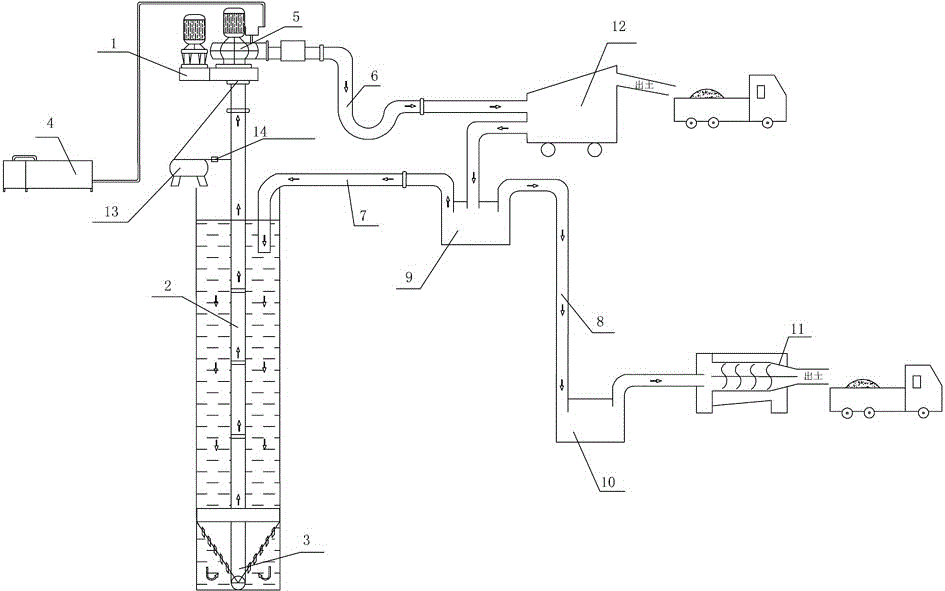
[0026] Embodiment one: see figure 1 As shown, a mud reduction treatment system is composed of a mud extraction device, a mud removal and purification device, and a chemical treatment device connected in sequence.

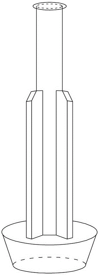
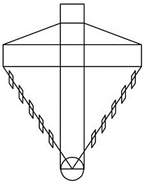
[0027] see figure 1 , the mud pumping device includes a high-torque power unit 1, a large-diameter hollow drill pipe 2, a scraper drill bit 3, a vacuum pump 4, a dredge pump 5, a reducer 14, a hoist 13, and a mud discharge pipe 6. The power unit 1 Drive the hollow drill pipe 2 to rotate, the hoist 13 cooperates with the reducer 14 to drive the hollow drill pipe 2 to move up and down, the inlet of the dredge pump 5 is connected to the inner cavity of the hollow drill pipe, and the outlet of the dredge pump 5 passes through the mud discharge pipe 6 Connect to the feed port of the desilting and purifying device. see figure 2 , in order to make the operation stable, the hollow drill rod is provided with a counterweight. see image 3 , the scraper bit is provided w...


PUM

PropertyMeasurementUnit
diameteraaaaaaaaaa

Abstract

The invention discloses a slurry reduction treatment system. The system consists of a slag slurry pumping device, a mud removal purification device and a chemical agent treatment device which are sequentially connected, and is characterized in that the mud removal purification device comprises a slurry storage tank, a double-layer screen arranged above the slurry storage tank, a main unit slag slurry pump, a cyclone, a middle storage tank and a first slurry tank, wherein the double-layer screen consists of a double-layer screen coarse screening layer at the lower part and a double-layer screen fine screening layer at the upper part; a feed opening of the mud removal purification device is positioned above the double-layer screen coarse screening layer; the slurry storage tank is connected to the cyclone through the main unit slag slurry pump; an overflow opening of the cyclone is communicated with the middle storage tank; an underflow opening of the cyclone is positioned above the double-layer screen fine screening layer; a slurry outlet of the middle storage tank is communicated with the first slurry tank. According to the system, slurry and slag can be effectively separated, the slurry can be reutilized, mud-water separation treatment can also be performed on the slurry by virtue of a chemical agent and a centrifugation method, and moreover, separation effects are ensured.

Description

technical field [0001] The invention relates to a mud processing method, in particular to a method for reducing the amount of construction mud. Background technique [0002] During building construction, for example during the construction of pile foundations, a large amount of mud is produced. Construction mud has a high water content (usually up to 70% to 80%), which is difficult to handle and will have adverse effects on the environment. Therefore, it is necessary to reduce the amount of mud to reduce the cost of mud transportation, reduce environmental pollution and realize the recycling of water resources. [0003] In the article "Application of centrifuge system in the process of construction mud reduction" in the fifth issue of "Construction Technology" in 2015, a centrifuge treatment system is disclosed, which consists of a mud inlet pump, a decanter centrifuge, and a dosing device. Composed of five components, compound feeding device and conveyor, the construction...

Claims


Application Information

Patent Timeline
Patent Type & Authority Applications(China)
IPC IPC(8): C02F11/00C02F11/12C02F11/14
CPCC02F11/00C02F11/121C02F11/14C02F2303/06
Inventor 程月红张翯牛洁雯
Owner ZHONGYIFENG CONSTR GRP
Learn More