
Method for constructing block-integrating air-layer-free air permeable type sandwich wall

An air layer, sandwich wall technology, applied in the direction of walls, buildings, building components, etc., can solve the problems of reducing the structural stability and thermal insulation performance of the wall, affecting the use of households, and growing hair and mildew on the wall, so as to improve the overall performance, Reduce construction difficulty and enhance overall effect

Inactive Publication Date: 2016-08-10
HARBIN DACHENG GREEN BUILDING TECH DEV
View PDF2 Cites 3 Cited by
  • Summary
  • Abstract
  • Description
  • Claims
  • Application Information

AI Technical Summary

Problems solved by technology

[0010] In order to solve the problem that the rainwater and moisture in the heat preservation layer of the existing sandwich wall are difficult to discharge, which will cause the wall to become moldy and deteriorate, reduce the structural stability and heat preservation performance of the wall, and affect the use of residents, the present invention further proposes agglomeration Masonry method of pattern-free air layer breathing sandwich wall

Method used


Image

  • Method for constructing block-integrating air-layer-free air permeable type sandwich wall
  • Method for constructing block-integrating air-layer-free air permeable type sandwich wall
  • Method for constructing block-integrating air-layer-free air permeable type sandwich wall

Examples


specific Embodiment approach 1

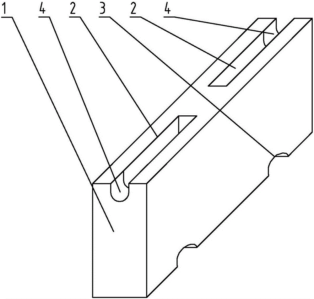
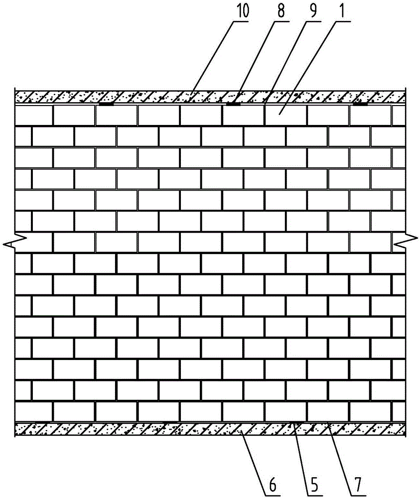
[0028] Specific implementation mode one: combine Figure 1 to Figure 7 To illustrate this embodiment, the method for building a block-mode air-layer-free breathing sandwich wall in this embodiment is characterized in that: the method includes the following steps:

[0029] Step 1: Masonry inner leaf wall: first lay the bottom skin gray joint 7 on the upper end surface of the bottom lintel 6, and build the inner leaf wall on the inner side of the bottom skin gray joint 7;

[0030] Step 2: laying the insulation layer: laying a layer of insulation layer on the outer surface of the inner leaf wall;

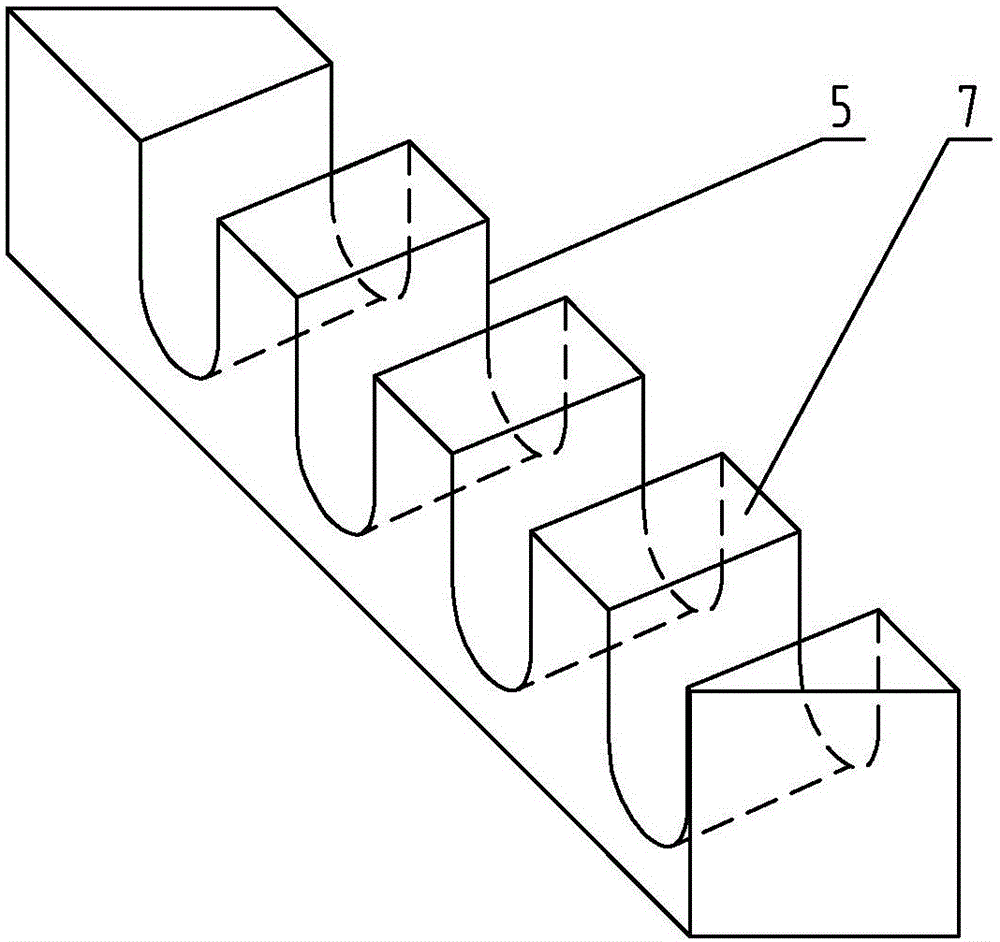
[0031] Step 3: Set air intake through holes 5: set a group of air intake through holes 5 on the front face of the bottom skin gray seam 7, each air intake through hole 5 is U-shaped, and the upper end surface of each air intake through hole 5 They are respectively flush with the upper end faces of the bottom skin gray seams 7, and the horizontal distance between two adjacent air intak...

specific Embodiment approach 2

[0041] Specific implementation mode two: combination Figure 1 to Figure 7 To describe this embodiment, in the third step of this embodiment, each air intake through hole 5 is provided with a first filter. The undisclosed technical features in this embodiment are the same as those in the first embodiment. Such a design can effectively prevent sundries and insects from entering and blocking the air outlet through hole 8 .

specific Embodiment approach 3

[0042] Specific implementation mode three: combination Figure 1 to Figure 7 Describe this embodiment, the axis of each air intake through hole 5 along the length direction in the step three of this embodiment forms an acute angle with the front end face of the bottom skin gray seam 7, and the front and rear end faces of each air intake through hole 5 Staggered settings. The undisclosed technical features in this embodiment are the same as those in the first or second specific embodiment. This design can effectively prevent rainwater from splashing into the wall.


PUM


Abstract

The invention relates to a masonry method of an air-layer-breathing-free sandwich wall in agglomerate mode, which relates to a wall masonry method. The invention aims to solve the problem that the rainwater and moisture in the thermal insulation layer of the existing sandwich wall are difficult to discharge, which causes the wall to grow hairy and moldy, deteriorate, reduce the structural stability and thermal insulation performance of the wall, and affect the use of residents. Masonry method: build the inner leaf wall; lay the insulation layer; set the air intake through hole; build the outer leaf wall by masonry; set the air outlet through hole; set the tie bars; set the decorative surface. The invention is used for the masonry of air-layer-free breathing sandwich walls.

Description

technical field [0001] The invention relates to a method for building a wall, in particular to a method for building a sandwich wall without air layer breathing in an aggregate mode. Background technique [0002] At present, there are mainly four methods of energy-saving and thermal insulation of building exterior walls in my country: single material wall, internal thermal insulation composite wall, external thermal insulation composite wall and sandwich composite wall. [0003] A single-material wall is to use the good thermal and other mechanical properties of a certain material to achieve the energy-saving goal required by the national energy-saving design standards, such as the clay brick wall of a traditional brick-concrete house. [0004] The inner thermal insulation composite wall is glued and built with some kind of thermal insulation material on the inner side of the outer wall to obtain the designed thermal resistance. [0005] The external thermal insulation comp...

Claims


Application Information

Patent Timeline
IPC IPC(8): E04B2/14F24F7/04
CPCE04B2/14F24F7/04
Inventor 王凤来刁领双孙绪杰
Owner HARBIN DACHENG GREEN BUILDING TECH DEV
Learn More