
Speed reducer special for efficient granulator

A technology of reducer and granulator, which is applied in the direction of mechanical equipment, gear lubrication/cooling, belt/chain/gear, etc. It can solve the problems of power loss, friction parts service life, reducer temperature rise, small heat dissipation area, etc.

Active Publication Date: 2016-08-10
ZHEJIANG HUIXIN DRIVING MACHINE
View PDF8 Cites 2 Cited by
  • Summary
  • Abstract
  • Description
  • Claims
  • Application Information

AI Technical Summary

Problems solved by technology

The reducer is a main power and transmission mechanism of the granulator, but in the actual production process, due to the limitation of the maintenance, installation and use environment of the granulator, most of the reducers used in the granulator have high energy consumption and low energy consumption during the transmission process. efficiency
In addition, because the existing granulator is mainly set up with a welded base, which wraps the right-angled shaft gearbox in the inner cavity, due to the small heat dissipation area of ​​the spiral bevel gear input seat and the surface of the whole box, and the time of more than 16 hours Continuous operation, full-sealed grease lubrication of rolling wheel bearings results in increased heat transfer from the shaft to the reducer, and the temperature of the reducer rises above 40°C, resulting in power loss due to expansion and even the service life of the friction parts. Negative impact
Therefore, providing a reducer suitable for installation in a high-efficiency pellet machine to overcome the defects of high energy consumption, low efficiency, and poor heat dissipation in the prior art has always been the direction of efforts of people in the industry.

Method used


Image

  • Speed reducer special for efficient granulator
  • Speed reducer special for efficient granulator

Examples


Embodiment Construction

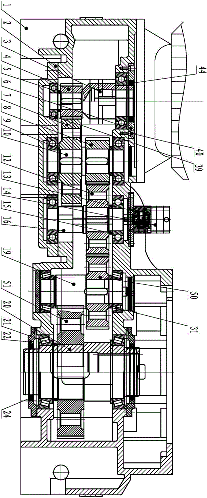
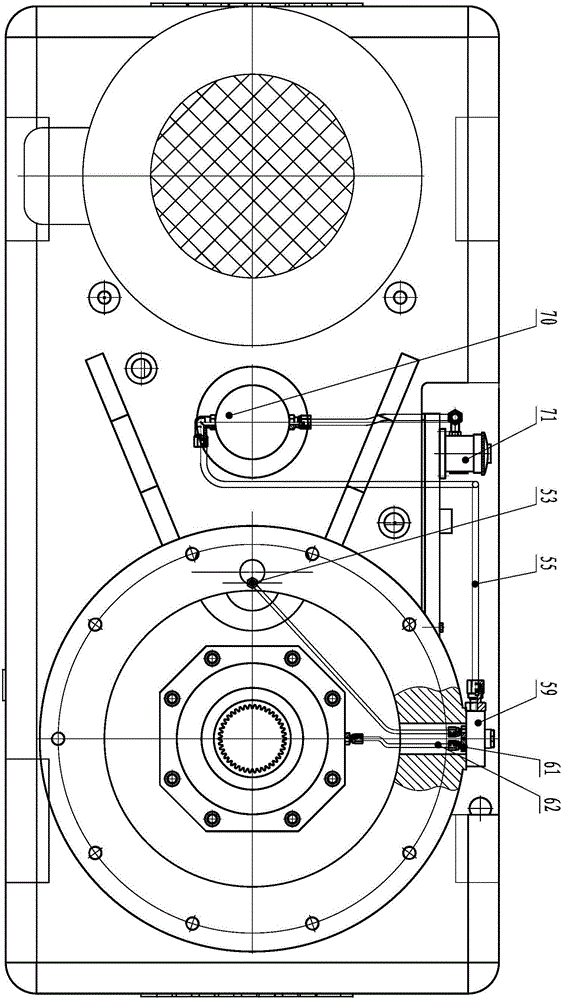
[0012] See attached figure 1 , 2 Shown is a special reducer for high-efficiency granulator according to the present invention, which includes a reducer casing 1, in which a coupling shaft 3, a secondary intermediate shaft 10, a tertiary intermediate shaft 16, and a third intermediate shaft are arranged in parallel in sequence. Stage gear shaft 19, hollow shaft 20, the input pinion 4 is installed on the coupling shaft 3 through a flat key, and the intermediate pinion 8 and the input pinion meshed with the input pinion 4 are installed on the secondary intermediate shaft 10 through a flat key. The bull gear 7, the three-stage intermediate shaft 16 is equipped with the intermediate bull gear 12 meshed with the intermediate pinion 8 through the flat key, and the three-stage large gear 12 meshed with the intermediate bull gear 12 is installed on the three-stage pinion shaft 19 through the flat key. Gear 50, the hollow shaft 20 is equipped with the output bull gear 51 that is meshed...


PUM


Abstract

The invention aims at providing a speed reducer special for an efficient granulator. The speed reducer comprises a speed reducer box body. A connecting shaft, a second-level intermediate shaft, a third-level intermediate shaft, a third-level gear shaft and a hollow shaft are sequentially arranged in the speed reducer box body in parallel. An input small gear is installed on the connecting shaft. An intermediate small gear and an input large gear engaged with the input small gear are installed on the second-level intermediate shaft. An intermediate large gear engaged with the intermediate small gear is installed on the third-level intermediate shaft. A third-level large gear engaged with the intermediate large gear is installed on the third-level gear shaft. An output large gear engaged with the third-level gear shaft is installed on the hollow shaft. The speed reducer box body comprises a bottom cover and a top cover covering the bottom cover. The two ends of the connecting shaft, the two ends of the second-level intermediate shaft and the two ends of the third-level intermediate shaft are supported on the bottom cover of the speed reducer through deep groove ball bearings. The two ends of the third-level gear shaft and the two ends of the hollow shaft are supported on the bottom cover through tapered roller bearings.

Description

technical field [0001] The invention relates to a reducer, in particular to a special reducer for a high-efficiency granulator. Background technique [0002] With the rapid consumption of fossil resources and the continuous deterioration of the ecological environment, countries around the world, especially major powers, have made the development of new energy and renewable energy the focus of a new round of industrial development. Biomass, as the only renewable resource that can convert gas, liquid and solid fuels and has a two-way cleaning effect, has attracted widespread attention from most countries in the world. During this process, pellet machines for the production of biomass pellets also began to play an important role in the market. The reducer is a main power and transmission mechanism of the granulator, but in the actual production process, due to the limitation of the maintenance, installation and use environment of the granulator, most of the reducers used in th...

Claims


Application Information

Patent Timeline
IPC IPC(8): F16H57/023F16H57/029F16H57/04
CPCF16H57/023F16H57/029F16H57/0404F16H57/0435F16H2057/02086Y02E50/30
Inventor 应成龙
Owner ZHEJIANG HUIXIN DRIVING MACHINE
Learn More