Device group control system

A technology of equipment and target equipment, which is applied in the field of equipment group control system to achieve the effect of improving operation stability and reliability and alleviating work pressure

Active Publication Date: 2016-08-10
GREE ELECTRIC APPLIANCES INC
View PDF8 Cites 14 Cited by
  • Summary
  • Abstract
  • Description
  • Claims
  • Application Information

AI Technical Summary

Problems solved by technology

[0004] In view of this, the object of the present invention is to provide an equipment group control system, which aims to overcome the above problems existing in the existing centralized group control mode, and improve the operation stability and reliability of group control systems such as air-conditioning machine rooms.

Method used


Image

  • Device group control system
  • Device group control system

Examples


Embodiment 1

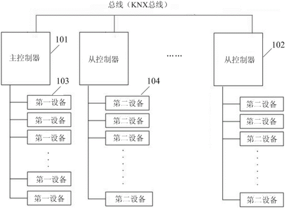
[0038] refer to figure 1 , figure 1 It is a schematic structural diagram of Embodiment 1 of a device group control system provided in this application, and the device group control system may include:

[0039] A master controller 101 and at least one slave controller 102; the master controller 101 and the slave controller 102 are respectively connected to a preset bus;

[0040] Access to at least one first device 103 of the main controller 101;

[0041] Access to at least one second device 104 of the slave controller 102;

[0042] The master controller 101 is configured to control the at least one first device 103 and the at least one slave controller 102 accordingly when receiving the first instruction;

[0043] The slave controller 102 is configured to control the at least one second device 104 when receiving a second instruction from the master controller 101 .

[0044] In this embodiment, the master controller 101 or the slave controller 102 may be a DDC (Direct Digita...

Embodiment 2

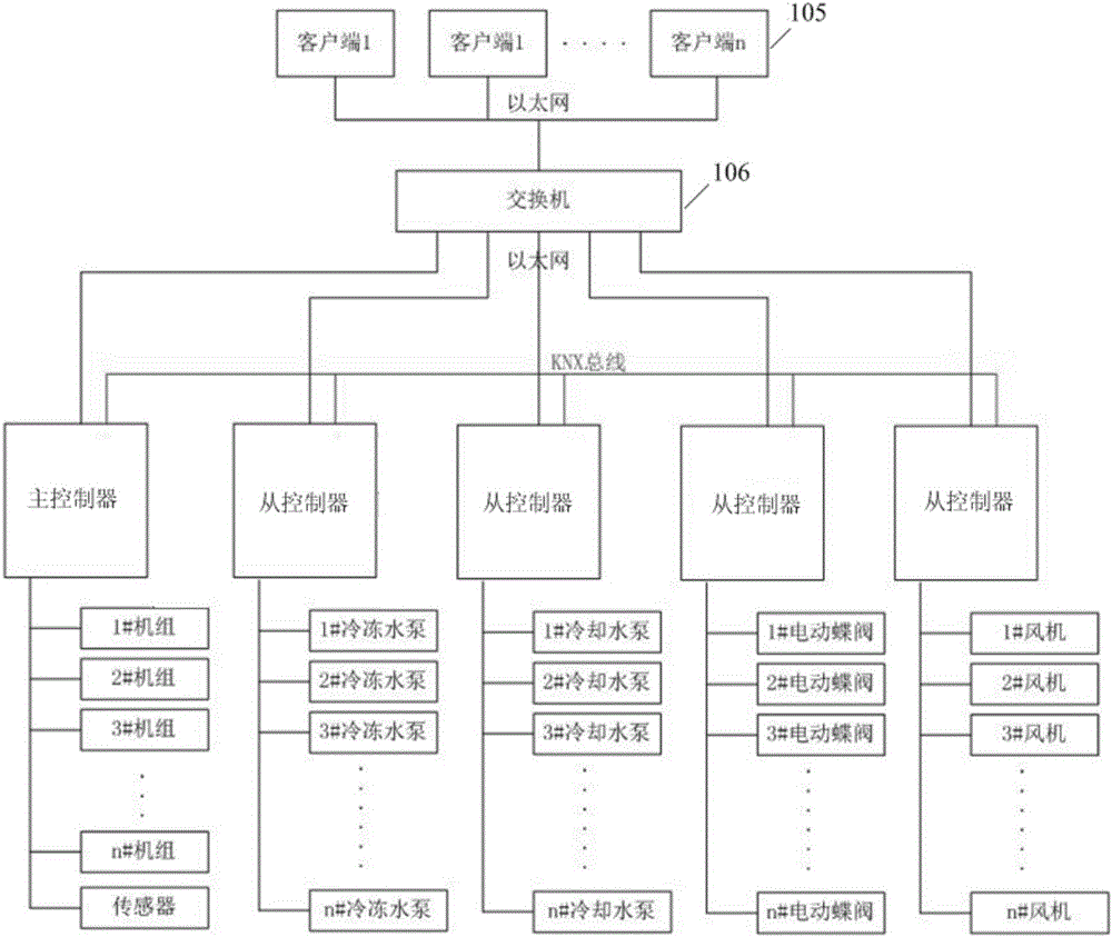
[0053] The main control trigger instruction received by the main controller, that is, the first instruction may be issued by a master control device. Based on this, refer to figure 2 Shown is a schematic structural diagram of Embodiment 2 of the device group control system of the present application. The system may also include:

[0054] a general control device 105, configured to issue the first instruction to the main controller;

[0055] The master controller and the at least one slave controller are respectively connected to the master control device 105;

[0056] The switch 106 is connected to the master control device 105;

[0057] The master controller and the at least one slave controller are connected to the master control device 105 through the switch 106 .

[0058] Specifically, the master controller and the slave controller can be connected to the switch 105 through Ethernet, and the switch 106 can also be connected to the master control device 105 through Ether...

Embodiment 3

[0062] Since the centralized control method in the prior art only uses a single controller, and each device in the group control system is connected to the single controller, once the single controller fails, the entire group control system will be paralyzed.

[0063] To solve this problem, in this embodiment, the slave controller is further configured to switch to be the master controller of the system when receiving the third instruction from the master control device.

[0064] Therefore, when the master controller in the system fails, the master control device can select a controller from the normal operating slave controllers to assume the role of the master controller based on the corresponding fault handling mechanism, and can issue the In the form of an instruction (the third instruction), it instructs the selected slave controller to switch roles so that it can perform the group control function of the master controller, so that even when the master controller of the sy...


PUM


Abstract

The invention discloses a device group control system. The device group control system comprises a main controller, at least one auxiliary controller, at least one first device and at least one second device, wherein the main controller and the auxiliary controllers are connected with a preset bus, the first devices are connected to the main controller, and the second devices are connected to the auxiliary controllers. The main controller is used for conduct corresponding controlling on the first devices and the auxiliary controllers when receiving a first instruction. The auxiliary controllers are used for conduct corresponding controlling on the second devices when receiving a second instruction of the main controller. Thus, the distributed control mode device group control system based on the main-auxiliary controllers is achieved, by arranging the multiple controllers (the main controller and the auxiliary controllers) in the device group control system, coordination control is conducted on device groups in the system, the working pressure of a single controller in a concentrated control mode is effectively relieved, and accordingly the operation stability and reliability of an air conditioner room and other group control systems can be improved.

Description

technical field [0001] The invention belongs to the technical field of equipment group control, and in particular relates to an equipment group control system. Background technique [0002] At present, group control systems such as group control systems for air-conditioning machine rooms generally adopt a centralized control method based on a single controller to control each connected device in the system, such as units, sensors, chilled water pumps, fans, etc. Among them, all connected The devices are all connected to the only one controller in the system - the main controller, which centrally controls each connected device. [0003] For large-scale air-conditioning equipment rooms, the number of equipment is generally large, which will correspondingly lead to greater working pressure on the single controller in the centralized control mode, that is, the main controller. Nowadays, the centralized control mode based on a single controller is due to the The working pressure...

Claims


Application Information

Patent Timeline
Patent Type & Authority Applications(China)
IPC IPC(8): F24F11/00
CPCF24F11/30F24F11/54F24F11/62
Inventor 钟兴宁王聪何玉雪姜春苗杨金龙丁文涛
Owner GREE ELECTRIC APPLIANCES INC
Why Eureka
Try Eureka