
Multi-target radar detection method

A detection method and multi-target technology, applied in measurement devices, radio wave measurement systems, radio wave reflection/re-radiation, etc., can solve the problems of complex algorithm, complex implementation, poor reliability, etc., to achieve simple engineering and simple implementation , the effect of high reliability

Active Publication Date: 2016-08-10
ZHEJIANG DAHUA TECH CO LTD
View PDF6 Cites 29 Cited by
  • Summary
  • Abstract
  • Description
  • Claims
  • Application Information

AI Technical Summary

Problems solved by technology

The algorithm of this scheme is more complex, and the conditions for its realization are more stringent. It is required that the upper and lower frequency bands of each modulation signal can accurately detect the target information, and the error of the final measured target information is relatively large.
In fact, whether it is a target close to the radar or a target far away from the radar, there is always a frequency band in the echo signal that is not ideal. The probability of detecting reliable target information at the same time in the four frequency bands of the two modulation signals is not high. Even if the detection error is large
[0004] Another solution is: the radar modulation signal uses the mixed signal of CW (Continuous Wave, single-frequency continuous wave) and FMCW sawtooth wave signal, and the radar echo signal is mixed at the receiving end to obtain the required intermediate frequency. Signal, when processing the intermediate frequency signal, perform FFT operation on the I and Q signals separately and then perform target detection. This solution is costly, the algorithm is complex, and the engineering implementation is difficult, and it is impossible to distinguish between targets that are close to and far from the radar.
[0005] Therefore, the deficiencies of the prior art are: high cost, complex implementation, poor reliability

Method used


Image

  • Multi-target radar detection method
  • Multi-target radar detection method
  • Multi-target radar detection method

Examples


Embodiment Construction

[0044] Specific embodiments of the present invention will be described below in conjunction with the accompanying drawings.

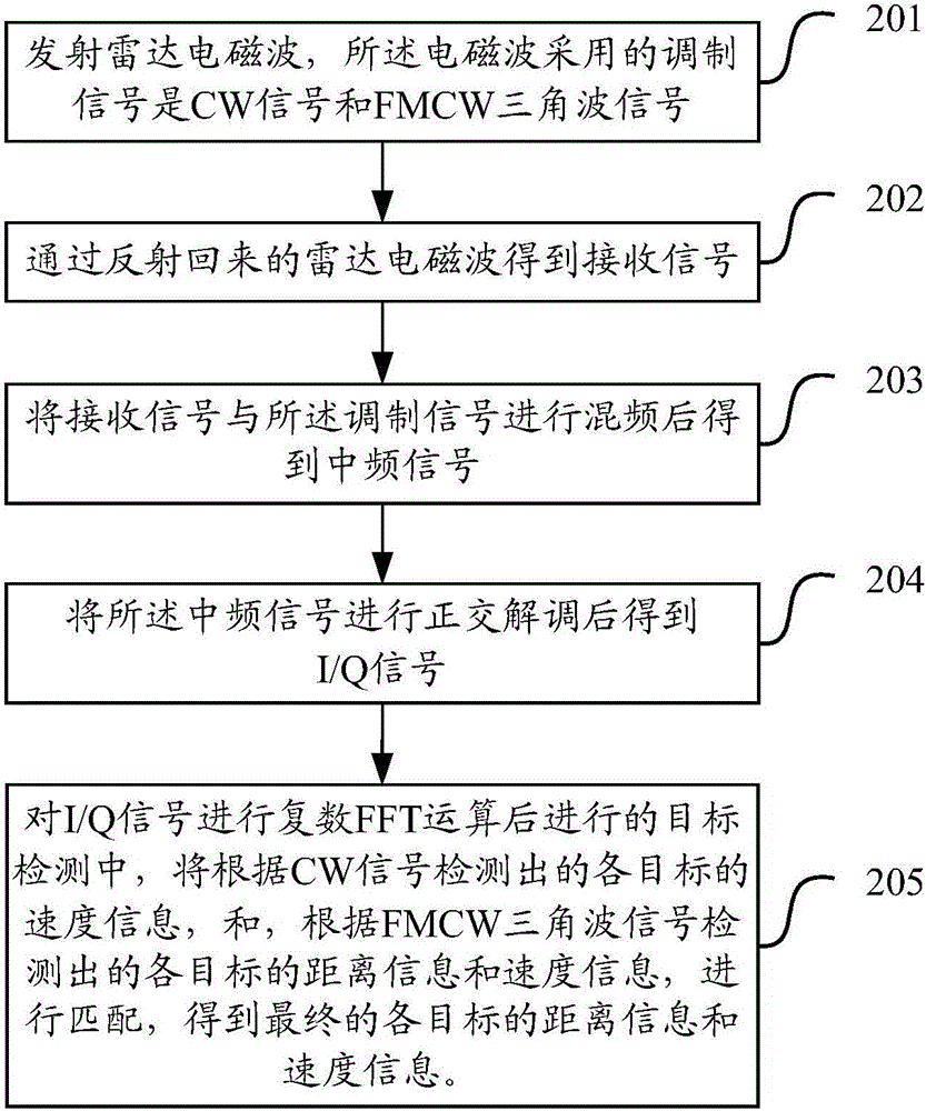
[0045] figure 2 A schematic diagram of the implementation process for the radar detection method, as shown in the figure, may include the following steps:

[0046] Step 201, transmitting radar electromagnetic waves, the modulation signals used by the electromagnetic waves are CW signals and FMCW triangular wave signals;

[0047] Step 202, obtaining a received signal through the reflected radar electromagnetic wave;

[0048] Step 203, mixing the received signal and the modulated signal to obtain an intermediate frequency signal;

[0049] Step 204, performing quadrature demodulation on the intermediate frequency signal to obtain an I / Q signal;

[0050] Step 205, in the target detection after the complex FFT operation is carried out on the I / Q signal, the speed information of each target detected according to the CW signal, and the distance information...


PUM


Abstract

The invention discloses a multi-target radar detection method, comprising steps of transmitting a radar electromagnetic wave, wherein the modulation signals adopted by the electromagnetic wave are a single frequency continuous-wave CW signal and a frequency modulation continuous wave FMCW triangular wave signal, obtaining a reception signal through the radar electromagnetic wave reflected back, performing frequency mixing on the reception signal and the modulation signal to obtain an intermediate frequency signal, obtaining an I / Q signal after performing quadrature demodulation on the intermediate frequency signal, performing matching according to speed information of various targets which is detected by the CW signal and the distance information and speed information of various targets which are detected by the FMCW triangle wave signal after performing complex fast Fourier FFT operation on the I / Q signal to obtain final distance information and speed information of various targets. The multi-target radar detection method is low in cost, simple in realization and high in reliability.

Description

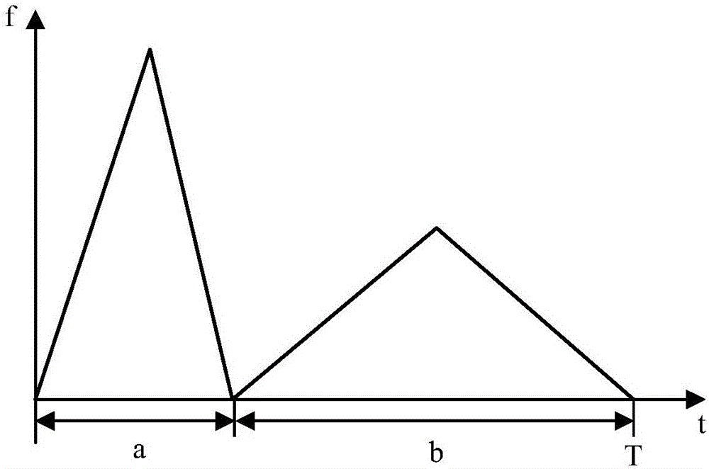
technical field [0001] The invention relates to the technical field of radar, in particular to a multi-target radar detection method. Background technique [0002] The traditional FMCW (Frequency Modulated Continuous Wave) system radar has serious distance and speed coupling, and it cannot accurately detect the speed and distance information of each target in a multi-target environment. Among the existing radar multi-target detection schemes, there are mainly the following two types: [0003] One solution is: the transmitting signal adopts the FMCW triangular wave modulation signal with variable period and the FMCW triangular wave modulation signal with variable frequency modulation slope, for example, figure 1 It is the FMCW triangular wave signal diagram of variable frequency modulation slope, the FMCW triangular wave modulation signal of variable frequency modulation slope in this scheme is as follows figure 1 shown. The algorithm of this scheme is more complicated, an...

Claims


Application Information

Patent Timeline
IPC IPC(8): G01S13/58
CPCG01S13/584
Inventor 李巧艳郑皓洲黄超孙文峰
Owner ZHEJIANG DAHUA TECH CO LTD
Learn More