
an optical cavity

A technology of optical resonator and gas laser, which is applied in the field of lasers, can solve problems affecting the stability of optical resonator and instability of optical resonator, and achieve the effects of protecting safety, ensuring stability, reducing shock and up and down vibration

Active Publication Date: 2018-06-26
CHANGCHUN INST OF OPTICS FINE MECHANICS & PHYSICS CHINESE ACAD OF SCI
View PDF3 Cites 0 Cited by
  • Summary
  • Abstract
  • Description
  • Claims
  • Application Information

AI Technical Summary

Problems solved by technology

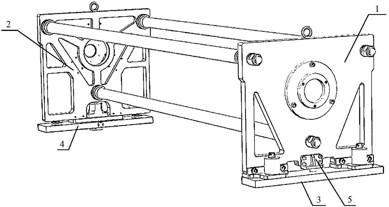
[0005] The optical resonant cavity of the prior art gas laser includes an output mirror, a reflector, an output mirror support plate for fixing the output mirror, a reflector support plate for fixing the reflector, and three indium steel pipes for connecting the output mirror support plate and the reflector support plate , the output mirror support plate is fixed by the output mirror support plate, and the reflector support plate is fixed by the reflector support plate. When the gas laser is used under vehicle conditions or under severe temperature changes, the optical resonator will be damaged due to body vibration or temperature changes. Instability, affecting the stability of the optical resonator

Method used


Image

  • an optical cavity
  • an optical cavity
  • an optical cavity

Examples


Embodiment Construction

[0050] The invention discloses an optical resonant cavity to ensure the stability of the optical resonant cavity under vehicle conditions or severe temperature changes.

[0051] The following will clearly and completely describe the technical solutions in the embodiments of the present invention with reference to the accompanying drawings in the embodiments of the present invention. Obviously, the described embodiments are only some, not all, embodiments of the present invention. Based on the embodiments of the present invention, all other embodiments obtained by persons of ordinary skill in the art without making creative efforts belong to the protection scope of the present invention.

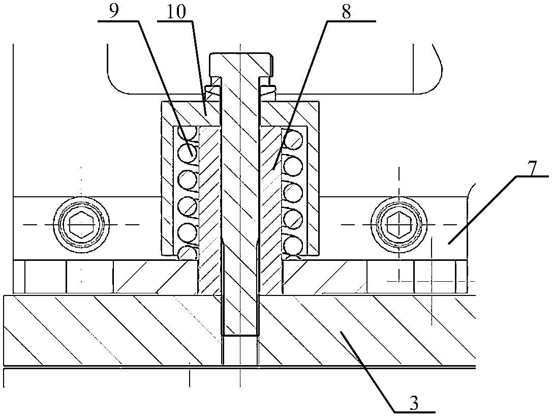
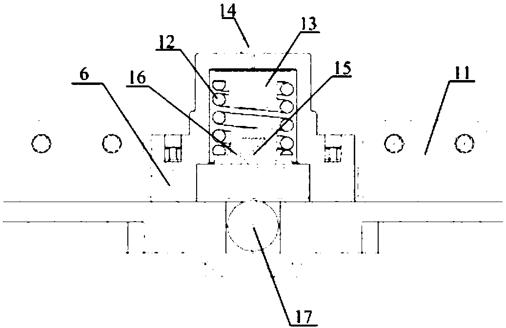
[0052] see Figure 1-Figure 4 , figure 1 Schematic diagram of the structure of the optical resonant cavity provided by the embodiment of the present invention; figure 2 Schematic diagram of the structure of the first buffer provided by the embodiment of the present invention; image 3 Sch...


PUM


Abstract

The invention discloses an optical resonant cavity, which is suitable for a gas laser, and includes an output mirror support plate, a reflection mirror support plate, an output mirror support plate and a reflection mirror support plate. The gas laser provided by the proposal adds positioning pins, a first buffer pieces, the second buffer piece and the limit block. Among them, the positioning pin can ensure the direction of the light output by the output mirror; the first buffer and the second buffer can reduce the shock and up and down vibration during vehicle transportation, and play a role in protecting the safety of the overall truss, output mirror and reflector, reducing the The damage to the gas laser ensures the stability of the optical resonant cavity under vehicle conditions; the mirror support plate can slide along the length of the resonant cavity. When the temperature changes greatly, the vehicle base will expand and contract. The movement of the supporting plate can eliminate the position change between the reflecting mirror supporting plate and the output mirror supporting plate caused by the expansion and contraction of the base, so as to ensure the stability of the entire truss.

Description

technical field [0001] The invention relates to the technical field of lasers, in particular to an optical resonant cavity. Background technique [0002] Gas lasers have broad application prospects in military fields, industrial processing, new materials, and nuclear physics. [0003] A gas laser is a device that uses gas as a working substance to generate laser light. It consists of three main parts: an optical resonant cavity, a discharge cavity and a power supply. The optical resonant cavity is a cavity in which light waves oscillate back and forth to provide optical energy feedback. It is usually composed of It consists of two flat or concave spherical mirrors perpendicular to the axis of the working medium. [0004] With a stable optical resonant cavity, the light will not escape out of the cavity laterally when it travels back and forth in the optical resonant cavity for any number of times. [0005] The optical resonant cavity of the prior art gas laser includes an ...

Claims


Application Information

Patent Timeline
Patent Type & Authority Patents(China)
IPC IPC(8): H01S3/08G02B7/198
CPCH01S3/08059G02B7/198
Inventor 杨贵龙邵明振张阔陈飞郭劲
Owner CHANGCHUN INST OF OPTICS FINE MECHANICS & PHYSICS CHINESE ACAD OF SCI
Learn More