
Stator flux linkage calculation method based on vector transformation and signal filtering

A technology of signal filtering and vector transformation, applied in the field of acceleration method control, estimation/correction of motor parameters, direct torque control, etc.

Active Publication Date: 2016-08-10
HUAZHONG UNIV OF SCI & TECH
View PDF4 Cites 15 Cited by
  • Summary
  • Abstract
  • Description
  • Claims
  • Application Information

AI Technical Summary

Problems solved by technology

The first compensation-based algorithm introduces the stator frequency ω e For amplitude and phase compensation, the observer performance depends on ω e Estimation accuracy, special treatment is required when the motor starts and the speed jumps; the feedback algorithm has a simple structure and does not require motor frequency parameters. However, considering the amplitude and phase distortion, the cutoff frequency of the algorithm is generally low, and it is not suitable for flux linkage DC The bias decay speed is slow and the system dynamic performance is poor
There are also literatures that propose second-order, third-order and other high-order filters to replace the algorithm of the pure integral link. The principle is consistent with the first-order LPF, and the performance of the flux calculation is not greatly improved. Moreover, the system is too complicated and the calculation amount increases a lot.
In addition to the flux linkage voltage model, some literatures have proposed the extended Kalman filter method based on the current model and the flux linkage observation model based on the full-order observer. Strong, with certain limitations

Method used


Image

  • Stator flux linkage calculation method based on vector transformation and signal filtering
  • Stator flux linkage calculation method based on vector transformation and signal filtering
  • Stator flux linkage calculation method based on vector transformation and signal filtering

Examples


Embodiment

[0041] The stator flux calculation method based on vector transformation and signal filtering of the present invention has excellent performance and wide application. The following takes the induction motor control system based on direct torque control as an example to illustrate its specific application. The system adopts the traditional direct torque control scheme based on hysteresis controller, adopts circular flux linkage trajectory, torque and flux linkage hysteresis jointly determine the output voltage vector; the system is speed closed loop control, and the motor speed is adjusted by PI controller. The rated power of the motor is 75.0kW, the rated voltage is 380V, the rated frequency is 50.0Hz, the rated flux linkage amplitude is 0.980Wb, and the rated torque is 470Nm.

[0042] Figure 7 The method for calculating the flux linkage of the present invention is applied to the output signal waveform when the direct torque control system runs at medium and high speed. The giv...


PUM


Abstract

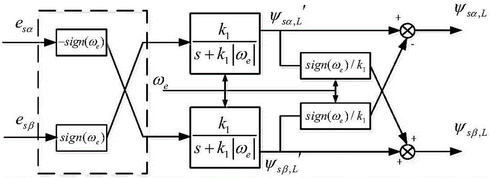
The invention discloses a stator flux linkage calculation method based on vector transformation and signal filtering. An alternating current motor stator flux linkage voltage model is used to carry out amplitude and phase transformation on an input back electromotive force vector to directly acquire an original stator flux linkage vector. Through signal filtering and compensation, an anticipant stator flux linkage is acquired. Vector transformation schemes based on a programmable low pass filter (LPF) and a band pass filter (BPF) are respectively designed. According to the principle that calculation flux linkage amplitude is converged to a given flux linkage value as soon as possible, an optimized function is acquired. LPF and BPF advantages are combined to acquire the flux linkage calculation method of the optimal performance. Furthermore, a BPF algorithm is decomposed, so that the structure of the optimized flux linkage algorithm is simplified. The calculation quantity is reduced, and system resources are saved. According to the invention, the algorithm has little dependence on motor parameters, and has the advantages of wide application range and high portability; and the calculated flux linkage has the advantages of small distortion and high accuracy.

Description

Technical field [0001] The invention belongs to the field of industrial automation, and specifically relates to a stator flux calculation method based on vector transformation and signal filtering for a three-phase AC motor control system. Background technique [0002] The research of AC motor flux linkage algorithm has a core position in the field of high-performance motor control. The voltage model of the flux linkage algorithm has the advantages of simple structure and little dependence on motor parameters, and is widely used in high-performance AC motor control systems. The pure integration link of the voltage model has the problem that the initial phase and DC drift make the integration output flux linkage distortion or integration saturation. Usually, a first-order low-pass filter (LPF) is used to replace the pure integration link. The flux linkage calculated by LPF has amplitude and phase errors. The focus of a large number of improved algorithm research is to eliminate t...

Claims


Application Information

Patent Timeline
Patent Type & Authority Applications(China)
IPC IPC(8): H02P23/14H02P23/30
CPCH02P23/14
Inventor 程善美刘莹刘江宁博文
Owner HUAZHONG UNIV OF SCI & TECH
Learn More