Equivalent micro-focus target

A focus target and micro focus technology, applied in the field of effective micro focus target, can solve the problems of limited improvement, increase ion beam current, reduce instantaneous temperature rise and average temperature rise, etc., so as to reduce deposition power density and increase ion beam current. The effect of strengthening and increasing the neutron yield

Inactive Publication Date: 2016-08-10
INST OF NUCLEAR PHYSICS & CHEM CHINA ACADEMY OF
View PDF7 Cites 1 Cited by
  • Summary
  • Abstract
  • Description
  • Claims
  • Application Information

AI Technical Summary

Problems solved by technology

[0003] There are currently three ways to improve the ability of the target to withstand the bombardment power of the ion beam: one is to use a swinging target to make the target surface mechanically swing. The advantage of this method is that the ion beam is no longer on the target surface without increasing the beam spot size. Only bombard a point, but a surface, the average power is greatly reduced, the ion beam current can be increased, and the characteristics of the point source remain unchanged; the disadvantage is that the speed of mechanical swing is not fast enough, the length of expansion is limited, the volume is large, and at the same time There is a pause at the edge of the rotation, and the transient temperature rise is relatively high. The deposition power density of a purely swinging target can be increased several times, and the increase is limited.
The second is "Rotating Target Intensive Neutron Source and Its Application" (Journal "Modern Physics Knowledge", No. 05, 1996) discloses a method of increasing the target area by using a rotating target. The...

Method used


Image

  • Equivalent micro-focus target

Examples


Embodiment 1

[0025] On the established 250keV, 2mA, 10mm beam spot diameter neutron generator, in order to obtain the effect of 5mm equivalent beam spot, under the condition of constant ion beam current intensity, the peak density of the beam current is increased by 4 times, and the heat dissipation When the conditions are unchanged, the temperature rise will increase by about 4 times, which will far exceed the allowable working temperature of the target. If the temperature rise of the target is kept constant, the ion beam current needs to be reduced by 4 times, and the neutron yield is reduced by 4 times. Using the equivalent micro-focus target of the present invention to transform the original neutron target: first adjust the focusing parameters of the beam optical system, increase the beam spot diameter to 33mm, increase the ion beam current intensity to 2.2mA, and reduce the beam current density by about 10 Then, after passing through the electric quadrupole lens, it becomes a fan-shap...

Embodiment 2

[0027] On the established 250keV, 2mA, 10mm beam spot diameter neutron generator, in order to obtain the effect of 7mm equivalent beam spot, under the condition of constant ion beam current intensity, the peak density of the beam current is increased by 2 times, and the heat dissipation When the conditions remain unchanged, the temperature rise will increase by about 2 times, and the life of the target will be greatly shortened. If the temperature rise of the target is kept constant, the ion beam current needs to be reduced by 2 times, and the neutron yield is reduced by 2 times. Using the equivalent micro-focus target of the present invention to transform the original neutron target: first adjust the focusing parameters of the optical system, increase the beam spot diameter to 33mm, increase the ion beam current intensity to 2.2mA, and reduce the beam current density by about 10 times. After passing through the electric quadrupole lens, it turns into a fan-shaped ion beam, fo...

Embodiment 3

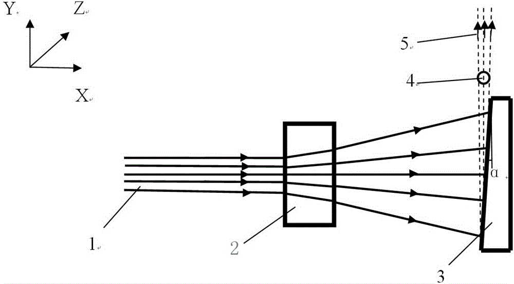
[0029] On the established 250keV, 2mA, 10mm beam spot diameter neutron generator, the ion source was modified to increase the ion beam current intensity by 11 times to 22mA, and the beam spot diameter increased to 33mm. Then adopt the technology of the present invention to transform the original neutron target: after the ion beam passes through the electric quadrupole lens, it becomes a fan-shaped ion beam, forming a bombardment area with a short direction of 10 mm and a length direction of about 110 mm on the target surface, and the bombardment of the moving target 3 The inclination angle α of the surface slope ranges from 3° to 15°, and the moving target 3 translates back and forth ±50mm, the peak density and average density of thermal power deposited on the target surface are reduced by 10 times, the temperature rise of the target surface is reduced by 10 times, and the service life of the target is greatly reduced Extended, the equivalent focal spot remains unchanged at 10m...


PUM

PropertyMeasurementUnit
Tilt angle αaaaaaaaaaa

Abstract

The invention provides an equivalent micro-focus target. After the accelerator accelerates the deuterium or deuterium-tritium mixed ion beam to the rated energy, the device uses a quadrupole lens to separate the beam spot of the large-diameter section into a beam parallel to the target surface. In the vertical direction, it is focused to the required micro-focal spot size, and defocused to a certain length in its vertical direction to form a fan-shaped ion beam. The fan-shaped ion beam bombards the moving target and produces an outgoing neutron beam equivalent to that of a microfocal spot neutron source in the spreading direction parallel to the target surface. Because the beam spot with large diameter section is expanded into a fan-shaped ion beam, the peak density of thermal power deposited on the target surface is greatly reduced, the average thermal power density is also greatly reduced, and the temperature rise of the target surface is greatly reduced accordingly. It is also possible to further increase the total power of the ion beam, thereby increasing the neutron yield, so as to reduce the equivalent spot size and increase the neutron yield at the same time. It is suitable for applications in high-yield accelerator neutron sources that require directional and point source characteristics.

Description

technical field [0001] The invention belongs to the field of nuclear technology and application, and in particular relates to an equivalent micro-focus target. Background technique [0002] The neutron generator with linear acceleration structure is a relatively mature technology, and there are many products. How to increase the neutron yield of this type of neutron generator, prolong the service life of the target, reduce the size of the focal spot, and improve the imaging quality, is an urgent problem to be solved. [0003] There are currently three ways to improve the ability of the target to withstand the bombardment power of the ion beam: one is to use a swinging target to make the target surface mechanically swing. The advantage of this method is that the ion beam is no longer on the target surface without increasing the beam spot size. Only bombard a point, but a surface, the average power is greatly reduced, the ion beam current can be increased, and the characteris...

Claims


Application Information

Patent Timeline
IPC IPC(8): H05H6/00
CPCH05H6/00
Inventor 李彦何小海娄本超唐君薛小明牟云峰李小飞胡永宏
Owner INST OF NUCLEAR PHYSICS & CHEM CHINA ACADEMY OF
Why Eureka
Try Eureka