Ultrasonic tooth cleaner treatment head and application thereof

A dental scaler and treatment head technology, which is applied in the directions of cleaning teeth, cleaning methods and appliances, dentistry, etc., can solve the problem that the treatment head cannot be used at high frequency, and achieves the advantages of reducing medical costs, improving treatment comfort, and improving heat dissipation effect. Effect

Inactive Publication Date: 2016-08-17
SHENZHEN BANGVO TECH
View PDF5 Cites 1 Cited by
  • Summary
  • Abstract
  • Description
  • Claims
  • Application Information

AI Technical Summary

Problems solved by technology

[0006] In view of the above technical problems, the purpose of the present invention is to break through the shortcomings of the existing ultrasonic scaler carbon fiber and plastic treatment heads that cannot be used at high frequencies, and provide a reasonable design and high-frequency use ultrasonic scaler treatment head structure. It greatly reduces the work intensity of medical staff and the treatment time of patients, which can effectively improve the doctor's work efficiency and treatment comfort

Method used


Image

  • Ultrasonic tooth cleaner treatment head and application thereof
  • Ultrasonic tooth cleaner treatment head and application thereof
  • Ultrasonic tooth cleaner treatment head and application thereof

Examples


Embodiment 1

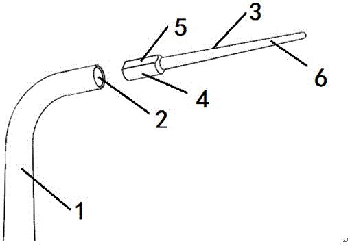
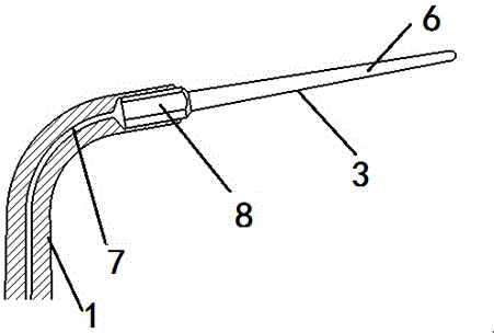
[0025] Such as figure 1 , 2 As shown, a treatment head for an ultrasonic dental scaler includes a base 1 and a working tip 3, the base 1 is provided with a flushing water injection pipeline 7, the working tip 3 is fixed on the base 1, and the fixing point between the working tip 3 and the base 1 is provided There is a flushing water injection hole connected to the flushing water injection pipeline 7, and the lower end of the flushing water injection pipeline 7 is connected with the scaler, and the rinse water of the scaler is introduced. The generated heat damages the working tip. The present invention adopts a unique water-cooling heat dissipation design structure. A flushing water injection hole is provided at the contact surface where the base 1 and the working tip 3 are fixed. The flushing water of the dental machine, the flushing water flows through the contact surface of the carbon fiber or plastic working tip and the metal base and is sprayed out, so that the flushing ...

Embodiment 2

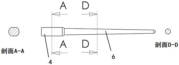
[0028] On the basis of embodiment 1 as preferred, such as Figure 1-4 As shown, the working tip 3 is composed of a root cylinder 4 and an end cylinder 6, the radius of the root cylinder 4 is greater than that of the end cylinder 6, the end cylinder 6 is a tapered columnar structure, and the root cylinder 4 is The columnar structure has flat root flats 5 on both sides of the columnar structure. The base 1 is provided with a working tip installation hole 2 matching the root cylinder 4, the flushing water injection pipe 7 is connected to the working tip installation hole 2, and the root flat 5 of the root cylinder 4 is connected to both sides of the working tip installation hole 2 The wall forms an arched flushing water injection hole, and the diameter of the base cylinder 4 of the carbon fiber or plastic working tip 3 is slightly larger than the diameter of the metal body installation hole. Since the carbon fiber or plastic is soft, the working tip 3 can be pressed into the base...


PUM


Abstract

The invention belongs to the field of dental medical equipment, and relates to a treatment head of an ultrasonic scaler and its application. The treatment head of the ultrasonic scaler includes a base and a working tip. The base is provided with a flushing water injection pipeline, and the working tip Fixed on the base, the contact surface between the working tip and the base is provided with a flushing water injection hole connected to the flushing water injection pipeline, and the working tip is made of carbon fiber or plastic material. The purpose of this invention is to break through the carbon fiber And plastic treatment head can not be used at high frequency, provides a reasonable design, can be used at high frequency ultrasonic scaler treatment head structure, greatly reducing the work intensity of medical staff and treatment time of patients, can be Effectively improve the doctor's work efficiency and treatment comfort.

Description

technical field [0001] The invention belongs to the field of dental medical equipment, and relates to a treatment head of an ultrasonic tooth scaler and an application thereof. Background technique [0002] With the continuous development of modern technology, ultrasonic dental scalers have been increasingly widely used in the field of stomatology. Although the implant technology is becoming more and more mature, whether the plaque on the implant surface above the gingival attachment can be effectively controlled is still an important factor in determining the long-term success rate of implant treatment. Because the metal treatment head will scratch the surface of the implant, resulting in a rough surface that is easy for plaque to adhere to, it is generally not used for cleaning the implant. Commonly used implant cleaning tools are hand-used plastic or carbon fiber instruments. However, limited by shape and volume, hand instruments are inefficient and often cannot complet...

Claims


Application Information

Patent Timeline
Patent Type & Authority Applications(China)
IPC IPC(8): A61C17/20
CPCA61C17/20
Inventor 吴一凡陈皋黄轶凡谈一红盛家华
Owner SHENZHEN BANGVO TECH
Why Eureka
Try Eureka