Non-excavation reconstruction structure of oil tank
A technology for structural transformation and non-excavation, applied in layered products, glass/slag layered products, synthetic resin layered products, etc. The effect of environmental friendliness, improving work efficiency and shortening construction time
- Summary
- Abstract
- Description
- Claims
- Application Information
AI Technical Summary
Problems solved by technology
Method used
Image
Examples
Embodiment 1
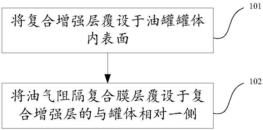
[0041] This embodiment provides a method for non-excavation transformation of oil tanks, which can mainly carry out non-excavation transformation of buried oil tanks. The method mainly includes: figure 1 The flow shown:
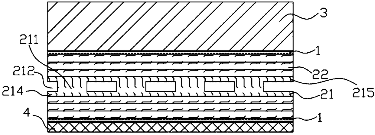
[0042] 101, the composite reinforcement layer 2 is covered on the inner surface of the oil tank body 3 through the adhesive layer 1 in the form of a prefabricated part. The composite reinforcement layer 2 includes: a skeleton penetrating layer 21, and glass covered on the skeleton penetrating layer 21 The fiber-reinforced layer 22, the frame penetration layer 21 includes: a frame 211 and a through cavity 212 between the frames 211 for placing oil and gas leakage detection components, such as figure 2 The non-excavation transformation structure of the oil tank is shown;
[0043] Specifically, the adhesive layer 1 is made of epoxy resin glue, and the prefabricated part can be a small-sized prefabricated sheet or a large-sized prefabricated sheet. The skeleton...
Embodiment 2
[0058] The difference between this embodiment and other embodiments mainly lies in:
[0059] Step 101 of this embodiment is specifically: splicing small-sized prefabricated sheets 300 to form the skeleton penetrating layer 21 and the glass fiber reinforced layer 22, including: splicing along the direction parallel to the axial direction of the tank body 3, and 3 Splicing in the circumferential direction. When the tank body 3 is a regular cylindrical tank body, the size of the small-sized prefabricated sheet 300 meets the following requirements: the size in the length direction is usually smaller than the length of the tank body 3 in the axial direction, and the size in the width direction is also smaller than that of the tank body 3 in the axial direction. less than the perimeter of the tank body 3 in the circumferential direction, such as Figure 11 shown.
Embodiment 3
[0061] The difference between this embodiment and other embodiments mainly lies in:
[0062] In this embodiment, the glass fiber reinforced layer 22 is located on one or both sides of the skeleton 211, and the glass fiber reinforced layer 22 can be made of glass fiber woven cloth soaked with epoxy resin glue or glass short fiber reinforced TPU instead of the skeleton through The panel and / or bottom plate of the layer 21, the unit structure formed by the combination of the skeleton penetrating layer 21 and the glass fiber reinforced layer 22 is combined through the splicing groove 213,
[0063] Then the corresponding step 101 is specifically:
[0064] Splicing in the form of small-sized prefabricated sheets 300 to form the composite reinforcement layer 2 includes: splicing along the direction parallel to the axial direction of the tank body 3, and splicing along the circumferential direction of the tank body 3, or prefabricated in a large size The sheets 100 are spliced to f...
PUM
 Abstract
Description
Claims
Application Information
 - R&D
- Intellectual Property
- Life Sciences
- Materials
- Tech Scout
- Unparalleled Data Quality
- Higher Quality Content
- 60% Fewer Hallucinations
Browse by: Latest US Patents, China's latest patents, Technical Efficacy Thesaurus, Application Domain, Technology Topic, Popular Technical Reports.
© 2025 PatSnap. All rights reserved.Legal|Privacy policy|Modern Slavery Act Transparency Statement|Sitemap|About US| Contact US: help@patsnap.com


