Single pipe loading and unloading arm for low-temperature ship
A loading and unloading arm, single-pipe technology, used in packaging, distribution devices, transportation and packaging, etc., can solve the problems of large temperature difference and large internal stress in the support structure and pipeline system, to eliminate internal stress, ensure safety, and design reasonable Effect
- Summary
- Abstract
- Description
- Claims
- Application Information
AI Technical Summary
Problems solved by technology
Method used
Image
Examples
Embodiment 1
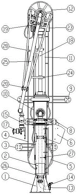
[0024] see Figure 1-Figure 4 , a low-temperature marine single-pipe loading and unloading arm, the single-pipe loading and unloading arm includes a support structure, a piping system, a hydraulic drive system, a maintenance platform 23, a nitrogen purge system 14, an emergency release system 15, a hydraulic substation 2, and an upper sheave 12. The steel wire rope 4 and the lower sheave 5, the steel wire rope is arranged between the upper sheave and the lower sheave, the support structure is used to support the pipeline system of the entire single-tube loading and unloading arm, and the maintenance platform is arranged on the loading and unloading arm In the upper part, the nitrogen purge system is set under the loading and unloading arm, and the hydraulic substation is set on the side of the column. The loading and unloading arm is also provided with a counterweight 6 arranged at the tail of the support box, a flange interface 13 arranged at the bottom, and a quick joint 17 ...
Embodiment 2
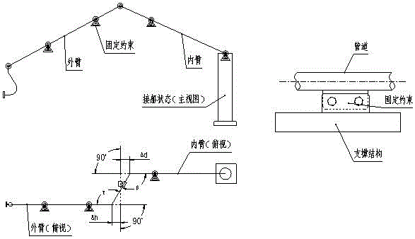
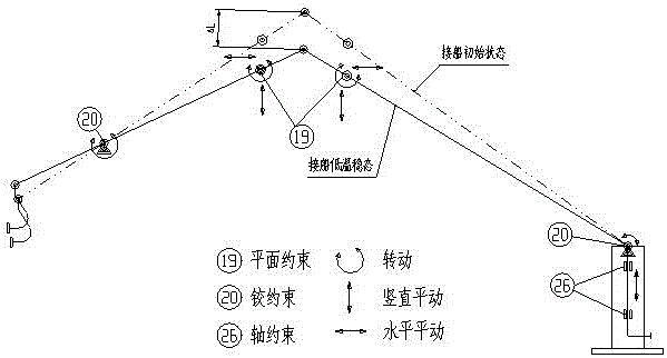
[0026] see figure 1 , Figure 4 , Pic 4-1 , as an improvement of the present invention, the hinge constraint includes a rib plate 201, a rib plate 202, a connecting pipe 203, a drip tray 204, a cover plate 205, a hinge shell 206, a retaining ring 207, a cold insulation block 208, a bottom plate 209 and The sealing plate 210, the connecting pipe is connected to the rib plate, the rib plate is provided with ribs, the drip tray is arranged between the connecting pipe and the cover plate, and a retaining ring, a cold insulation block and a sealing plate are arranged in the shell. Distributed at the ends of the inner and outer arm tubes see image 3 , which constrains all degrees of freedom of the pipe at this position except the rotation degree of freedom in the X direction, such as Figure 4 shown. At the same time, the hinge restraint has the design of drip tray and cold insulation block to minimize the transfer of cold energy.
Embodiment 3
[0028] see figure 1 , Figure 5 , Figure 5-1, as an improvement of the present invention, the planar constraints include a rib plate 191, a rib plate 192, a connecting pipe 193, a drip tray 194, a cover plate 195, a guide plate 196, and a thermal insulation pad 197, and the rib plate 191 is arranged on On the rib plate 192, the connecting pipe 193 is arranged between the drip tray 194 and the cover plate 195, and the outer surface of the guide plate is provided with a heat insulating plate, and the planar constraints are distributed at the ends of the inner arm pipe and the outer arm pipe, constraining the position of the pipe at this position Translation in the X direction, rotation degrees in the Y and Z directions, release the rotation degrees in the X direction and the translation degrees in the Y and Z directions at the same time, which can make the inner arm tube and the outer arm tube freely deformable. Such as Figure 5 shown. The confinement structure also has a...
PUM
 Abstract
Description
Claims
Application Information
 - R&D
- Intellectual Property
- Life Sciences
- Materials
- Tech Scout
- Unparalleled Data Quality
- Higher Quality Content
- 60% Fewer Hallucinations
Browse by: Latest US Patents, China's latest patents, Technical Efficacy Thesaurus, Application Domain, Technology Topic, Popular Technical Reports.
© 2025 PatSnap. All rights reserved.Legal|Privacy policy|Modern Slavery Act Transparency Statement|Sitemap|About US| Contact US: help@patsnap.com


