Natural gas dehumidifying device

A natural gas and straight pipe technology, applied in the field of pipeline-type conical annular flow channel subsonic natural gas dehumidifiers, can solve the problems of complicated structure and operation of the expander unit, and achieve the effect of eliminating adverse effects and reducing processing difficulty and cost.

Active Publication Date: 2016-08-17
INST OF MECHANICS - CHINESE ACAD OF SCI
View PDF5 Cites 4 Cited by
  • Summary
  • Abstract
  • Description
  • Claims
  • Application Information

AI Technical Summary

Problems solved by technology

Among them, the structure and operation of the expander unit are more complex than the J-T valve and supersonic separator

Method used


Image

  • Natural gas dehumidifying device
  • Natural gas dehumidifying device
  • Natural gas dehumidifying device

Examples


Embodiment 1

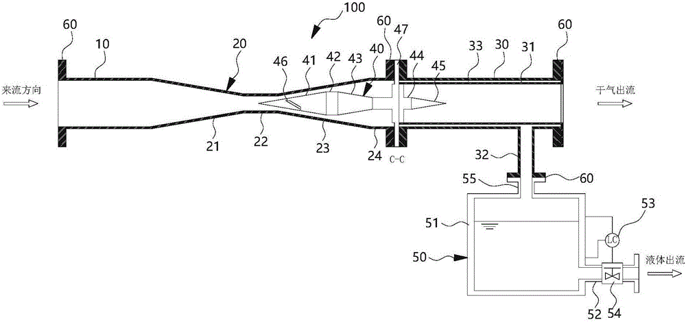
[0050] Taking a natural gas pipeline with a diameter of 150mm as an example, the total length of this natural gas dehumidifier is 1575mm, and four flange ports are used. One DN150 main air inlet is connected to the natural gas transmission channel by a straight pipe inlet section, and one DN150 is used to connect the rectifier section and straight pipe output section, a DN150 gas outlet is connected by the straight pipe output section and the natural gas transmission channel, and a DN50 is used for the outlet of the liquid discharge pipe.

Embodiment 2

[0052] The natural gas dehumidification device should be installed horizontally close to the wellhead or at the beginning of the gathering and transportation pipeline after the gas production pipes are assembled. The flange connection can replace a section of the delivery pipeline, and the installation is simple and convenient; the outlet of the liquid collection container is transported to the liquid storage tank through the infusion pipeline for further processing.

Embodiment 3

[0054] The on-site natural gas pipeline pressure is 3MPa, the gas temperature is 30 degrees Celsius, the actual measured pressure drop loss is about 20%, and the free liquid components can be separated by more than 95% after being treated by the natural gas dehumidification device, eliminating the liquid components in the pipeline transportation process Hazard of hydrate formation, freezing, clogging at elbows.


PUM

PropertyMeasurementUnit
diameteraaaaaaaaaa

Abstract

The invention provides a natural gas dehumidifying device. The natural gas dehumidifying device comprises a straight pipe inlet section, a straight pipe outlet section, a rectification section and a liquid collecting device, wherein one end of the straight pipe inlet section and one end of the straight pipe outlet section are connected with a natural gas pipeline, and the rectification section is arranged between the straight pipe inlet section and the straight pipe outlet section. The rectification section is of a variable-section structure, and a flow guide liquid distribution device is installed in the rectification section. The liquid collecting device is communicated with the interior of the straight pipe outlet section through a liquid discharging pipe so as to collect liquid separated from the straight pipe outlet section. In the natural gas dehumidifying device, the flow guide liquid distribution device is installed at the axis position of a flow channel composed of the rectification section and the straight pipe outlet section under positioning and fastening of a flange, and the speed of natural gas flowing through the flow channel is increased and decreased by changing the shape of a cavity formed by the inner wall of the pipeline and the flow guide liquid distribution device, so that the flowing speed and direction of in-coming flow natural gas are controlled, the pressure and temperature of the gas are changed, and thus liquid in the natural gas is separated out.

Description

technical field [0001] The invention relates to the field of energy collection, in particular to a pipeline type conical surface annular flow path subsonic natural gas dehumidifier. Background technique [0002] The vast majority of the world's natural gas is transported under pressure through copper pipelines. In order to ensure the normal operation of the gas pipeline, the water dew point and hydrocarbon dew point of the natural gas under the transmission pressure must be controlled below 0°C. [0003] For natural gas containing more natural gas liquid hydrocarbons and water, the method that can effectively remove the water in it at the same time is the temperature drop method, including throttling expansion refrigeration method and external refrigeration method. The former will lose the pressure energy of the natural gas itself, while the latter will not lose pressure, but refrigeration requires a large amount of power loss. [0004] General throttling expansion refrige...

Claims


Application Information

Patent Timeline
Patent Type & Authority Applications(China)
IPC IPC(8): C10L3/10
CPCC10L3/106
Inventor 李华吴应湘许晶禹张军郭军
Owner INST OF MECHANICS - CHINESE ACAD OF SCI
Why Eureka
Try Eureka