Al technical title is built by PatSnap Al team. It summarizes the technical point description of the patent document.
A rock splitter, fully automatic technology, applied in the direction of discharge machinery, mechanical equipment, fluid pressure actuating devices, etc., can solve the problems of inability to automatically control, prolong oil drainage time, and difficult to automate, and achieve simple and reliable structure and sealing. The effect of convenient construction and simple operation
Active Publication Date: 2016-08-17
GUANGDONG NACRE HYDRAULIC CO LTD
View PDF9 Cites 4 Cited by
Summary
Abstract
Description
Claims
Application Information
AI Technical Summary
This helps you quickly interpret patents by identifying the three key elements:
Problems solved by technology
Method used
Benefits of technology
Problems solved by technology
This phenomenon is particularly prominent in the initial stage of pressure relief, and it is a very troublesome problem in the field of hydraulic ultra-high pressure applications. The oil time is extended. In the field of hydraulic ultra-high pressure, the maximum rated working pressure of the ultra-high pressure electromagnetic directional valve currently available on the market can only reach 70MPa. When the pressure is higher, there is no corresponding electromagnetic directional valve product. 70MPa hydraulic pressure It is very difficult to automate the ultra-high pressure system, especially the hydraulic ultra-high pressure system above 100MPa, which cannot be automatically controlled by conventional hydraulic circuit means at present
Method used
Image
Click on the blue label to locate the original text in one second.
Reading with bidirectional positioning of images and text.
Examples
Embodiment Construction
[0027] The present invention will be further elaborated below in conjunction with accompanying drawing, wherein, the direction of the present invention is with figure 1 as standard.
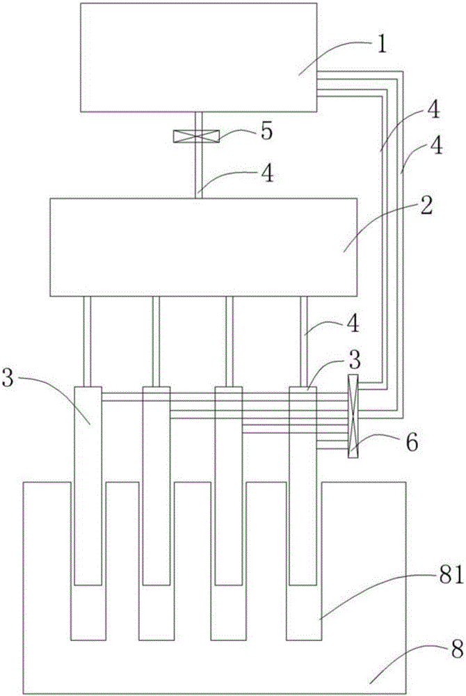
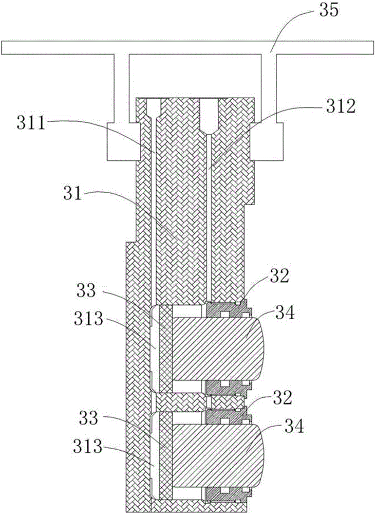
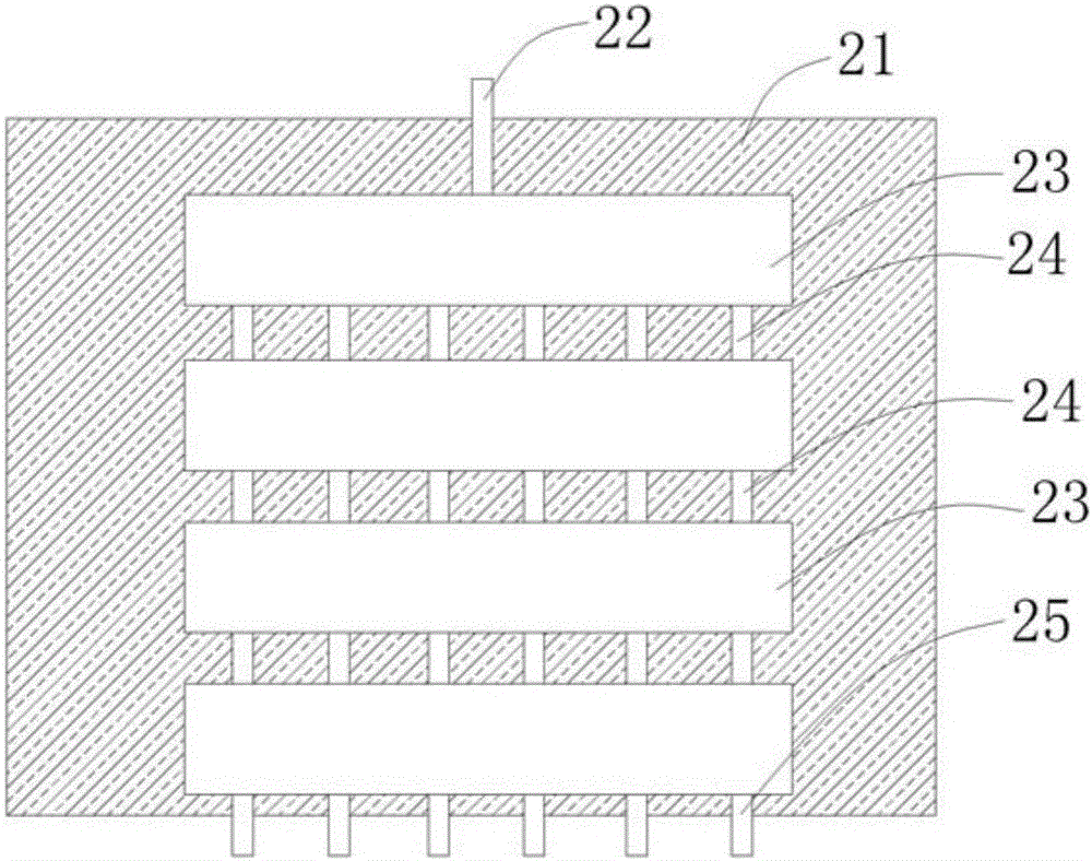
[0028] Such as figure 1 with 2 As shown, the fully automatic rock splitter of the present invention includes a hydraulic station 1, a distributor 2, four rock splitter rods 3, a hydraulic pipe 4, a one-way valve 5 and a pressure relief valve 6, and one of the branches of the hydraulic station 1 outputs high-pressure oil , the high-pressure oil flows into the distributor 2 in one direction through the one-way valve 5, and the distributor 2 injects the oil into the four cracking rods 3 (rodless cavity) at equal pressure, so as to realize the ejection of the four cracking rods 3 action to achieve the purpose of cracking rocks; another output branch of the hydraulic station 1 is high-pressure oil, and the high-pressure oil is injected into the pressure relief valve 6, so as to realize the opening o...
PUM
Abstract
The invention discloses a full-automatic stone cracking machine which is simple in structure, convenient to control, higher in work efficiency, better in stone cracking effect, higher in continuity and free of pollution and noise, and a pressure relief valve is controlled more conveniently and rapidly. The full-automatic stone cracking machine comprises a hydraulic station, multiple stone cracking bars, hydraulic pipes, a one-way valve and the pressure relief valve. The hydraulic station communicates with the one-way valve through the corresponding hydraulic pipe. The one-way valve communicates with the stone cracking bars through the corresponding hydraulic pipes so that oil liquid in the hydraulic station can be conveyed out to each stone cracking bar in the single direction. The stone cracking bars communicate with the pressure relief valve through the corresponding hydraulic pipes. The pressure relief valve communicates with the hydraulic station through the corresponding two hydraulic pipes; when each stone cracking bar is ejected out, the pressure relief valve is in a closed state; and when each stone cracking bar contracts, the oil liquid in the hydraulic station can control opening and closing of the pressure relief valve through one hydraulic pipe, and the oil liquid in each rock cracking bar flows back to the hydraulic station through the other hydraulic pipe.
Description
technical field [0001] The present invention relates to a valve, in particular, to a valve with simple structure, convenient control, higher work efficiency, better effect of rock cracking, stronger continuity, no pollution, no noise, and more convenient and quick control of the pressure relief valve. fully automatic rock cracker. Background technique [0002] Rock cracking equipment is a new type of construction equipment that splits rocks from the ground. At present, most construction methods use non-blasting construction methods, that is, using stone breakers, expansion agents, crushing equipment (such as breaking hammers, etc.), hook machines, and wire saws. , disc saw, flame cutting and water cutting equipment operation. [0003] Wire sawing, disc sawing, flame cutting, and water cutting belong to surface processing construction methods, which need to cut the entire section on the rock, which has low efficiency, high energy consumption, and less one-time investment in ...
Claims
Application Information
Patent Timeline
Application Date:The date an application was filed.
Publication Date:The date a patent or application was officially published.
First Publication Date:The earliest publication date of a patent with the same application number.
Issue Date:Publication date of the patent grant document.
PCT Entry Date:The Entry date of PCT National Phase.
Estimated Expiry Date:The statutory expiry date of a patent right according to the Patent Law, and it is the longest term of protection that the patent right can achieve without the termination of the patent right due to other reasons(Term extension factor has been taken into account ).
Invalid Date:Actual expiry date is based on effective date or publication date of legal transaction data of invalid patent.