Displacement measurement correction device and method
A technology of displacement measurement and correction device, which is applied in the field of measurement to achieve high precision, reduce influence and ensure high precision.
- Summary
- Abstract
- Description
- Claims
- Application Information
AI Technical Summary
Problems solved by technology
Method used
Image
Examples
Embodiment 1
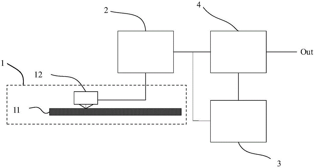
[0034] like figure 1 As mentioned above, the embodiment of the present invention provides a displacement measurement correction device, which is used to realize intelligent correction of displacement measurement and improve the precision of displacement measurement. Wherein, the device includes:
[0035] Grating displacement sensor 1, described grating displacement sensor 1 is used for carrying out displacement measurement;
[0036] Specifically, the grating displacement sensor 1 further includes: a scale grating 11 and a sensor reading head 12 , and the sensor reading head 12 is used to obtain displacement measurement information of a relative movement with the scale grating 11 .
[0037] An electronic control unit 2, the electronic control unit 2 is used to obtain the first displacement information measured by the grating displacement sensor 1;
[0038] Specifically, on the one hand, the electronic control unit 2 is used to obtain the first displacement information measure...
Embodiment 2
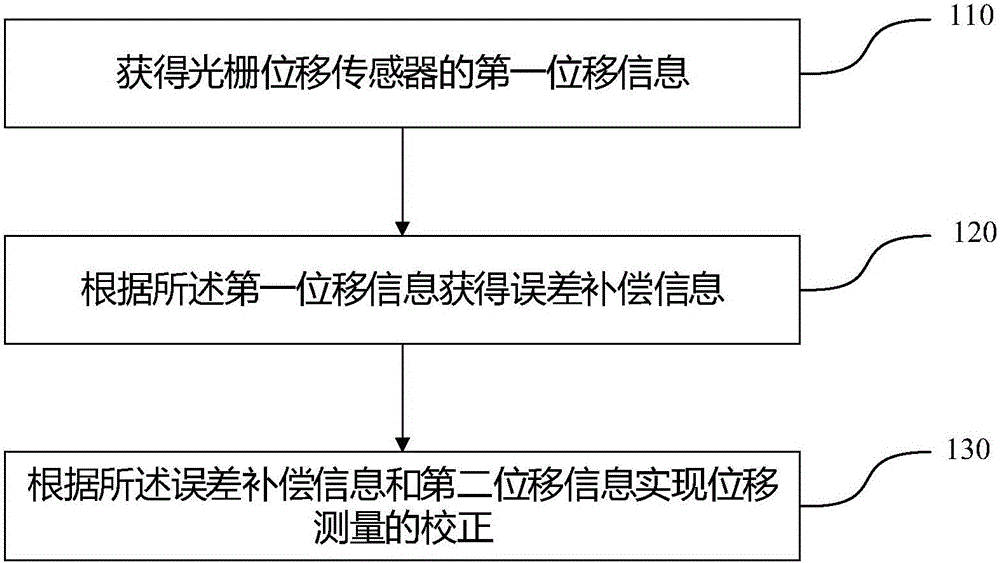
[0050] like figure 2 As shown, the embodiment of the present invention also provides a displacement measurement correction method, the method comprising:
[0051] Step 110: Obtain the first displacement information of the grating displacement sensor;
[0052] Step 120: Obtain error compensation information according to the first displacement information;
[0053] Step 130: Correct the displacement measurement according to the error compensation information and the second displacement information.
[0054] It should be noted that the core of this solution is to obtain error compensation information according to the first displacement information, and then use the error compensation information to compensate the second displacement information to complete the correction of the displacement measurement, so as to achieve the purpose of the embodiment of the present invention. Among them, the first displacement information can be regarded as the basic data, and the correction pa...
Embodiment 3
[0057] For a displacement measurement and correction device and method provided in the embodiments of the present invention, there are mainly the following three error sources in a specific usage scenario:
[0058] 1. Measurement system motion trajectory error;
[0059] 2. Measurement system periodic error;
[0060] 3. Measurement system drift error.
[0061] In order to better achieve the technical effect of ensuring high precision and high resolution while effectively reducing the cost of manufacturing and using the grating displacement sensor, the embodiment of the present invention also provides technical solutions for the above three errors, the specific content is as follows:
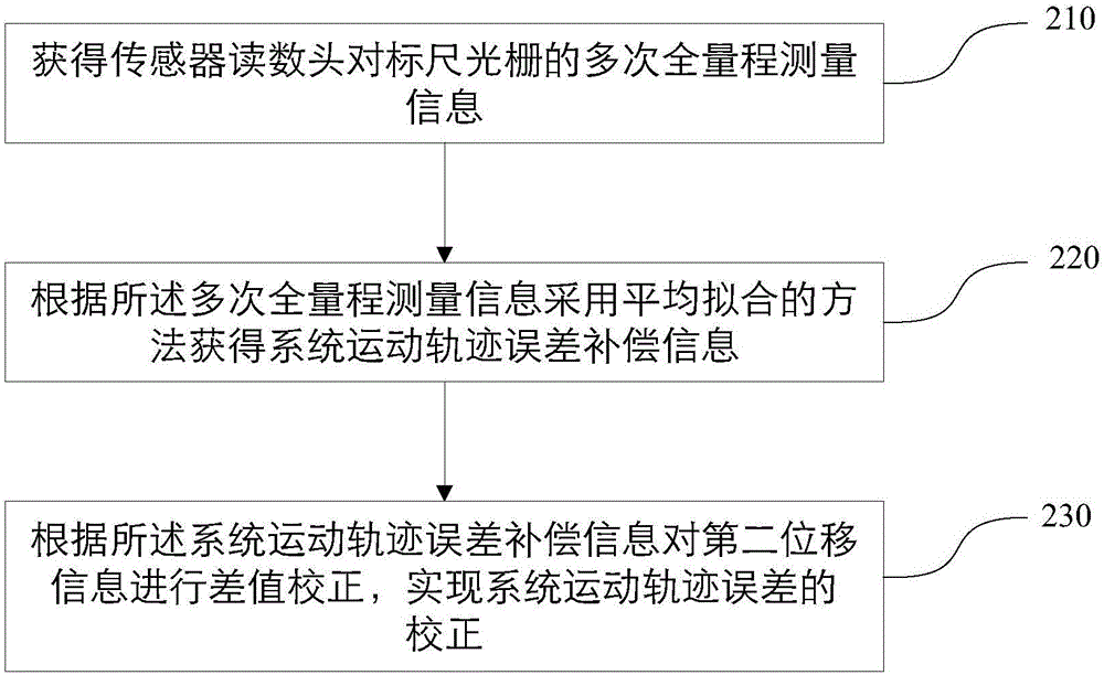
[0062] 1. Correction of motion trajectory error of measurement system
[0063] The correction of the movement track error of the measurement system is to correct the systematic installation error and deformation error of the scale grating relative to the grating displacement sensor reading head....
PUM
 Abstract
Description
Claims
Application Information
 - R&D
- Intellectual Property
- Life Sciences
- Materials
- Tech Scout
- Unparalleled Data Quality
- Higher Quality Content
- 60% Fewer Hallucinations
Browse by: Latest US Patents, China's latest patents, Technical Efficacy Thesaurus, Application Domain, Technology Topic, Popular Technical Reports.
© 2025 PatSnap. All rights reserved.Legal|Privacy policy|Modern Slavery Act Transparency Statement|Sitemap|About US| Contact US: help@patsnap.com


