20GHz ultra-wideband combiner provided with isolation degree

An ultra-wideband, combiner technology, applied in the microwave and radio frequency fields, can solve the problems that the frequency band is difficult to reach ultra-high frequency, the structure is complex, the input port has no isolation, etc. Excellent indicators

Inactive Publication Date: 2016-08-17
杨军
View PDF11 Cites 0 Cited by
  • Summary
  • Abstract
  • Description
  • Claims
  • Application Information

AI Technical Summary

Problems solved by technology

But there are two disadvantages: first, this network is lossy, the resistor network itself consumes 3dB of power, plus power points, so as to achieve a transmission loss of 6dB
Second, because of the high symmetry of the resistor network, there is no isolation between the two input ports
This patent is only for civilian mobile communication frequency bands, and the frequency bands are discrete, non-universal combiners
[0007] And Chinese patents: a broadband line combiner (CN203574080U), an ultra-broadband combiner (CN202196847U), an ultra-broadband combiner (CN201877551U), a broadband combiner (CN203339282U), a multi-band broadband combiner The circuit breaker (CN203242728U) and the broadband combiner (CN201766151U) are basically implemented by cavity, resonant rod (rod), filter, adjusting screw, coupling column and other methods. The structure is relatively complex, the volume is large, and the debugging is not difficult. Small and bulky equipment
[0008] The U.S. patent Broadband coupled-line power combiner / divider (US6472950B1) uses a coupled line array method to realize N-channel signal combination, which not only has a complex structure, but also has the problem that the frequency band is difficult to reach UHF

Method used


Image

  • 20GHz ultra-wideband combiner provided with isolation degree
  • 20GHz ultra-wideband combiner provided with isolation degree
  • 20GHz ultra-wideband combiner provided with isolation degree

Examples


Embodiment Construction

[0029] The present invention will be further described below with reference to the accompanying drawings and embodiments, and the mode of the present invention includes but not limited to the following embodiments.

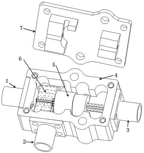
[0030] Such as figure 1 As shown, the present invention provides a 20GHz ultra-wideband combiner with isolation, which includes a metal box 4 , a cover 7 , a magnetic ring 5 and a microwave planar circuit board 6 . Both the microwave planar circuit board 6 and the magnetic ring 5 are built in the metal box 4; and the microwave planar circuit board 6 is connected to the first radio frequency connector 1, the second radio frequency connector 2 and the third radio frequency connector 3 respectively. The cover plate 7 covers the metal box body 4 .

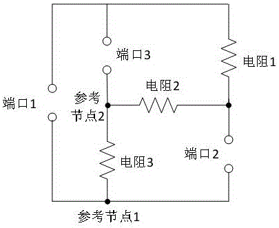
[0031] In the present embodiment, the microwave planar circuit board 6 is designed according to the principle of the 6dB bridge type mixed resistance network, and the principle of the 6dB bridge type mixed resistance netw...


PUM


Abstract

The invention discloses a 20GHz ultra-wideband combiner provided with an isolation degree, comprising a metal box body, a cover plate, a magnet ring and a microwave planar circuit board, wherein the microwave planar circuit board is designed based on the principle of a 6dB bridge type composite resistor network, a first radio frequency connector, a second radio frequency connector and a third radio frequency connector are respectively arranged on the metal box body, both the microwave planar circuit board and the magnet ring are built in the metal box body, the microwave planar circuit board is connected to the first radio frequency connector, the second radio frequency connector and the third radio frequency connector respectively, the magnet ring sleeves a position where the microwave planar circuit board is connected to the third radio frequency connector, and the cover plate covers the metal box body. The 20GHz ultra-wideband combiner provided with the isolation degree disclosed by the invention has the advantages of simple structure, small volume, low cost, good technical indicators, easiness for implementation and commissioning and capability of not only realizing 20GHz ultra wideband but also meeting requirements for applications in civil mobile communication, optical communication and some special frequency fields, and is provided with two input ports with a higher isolation degree.

Description

technical field [0001] The invention relates to the technical fields of microwave and radio frequency, in particular to a 20GHz ultra-wideband combiner with isolation. Background technique [0002] The combiner is a passive microwave device, mainly used for power combination and distribution. A combiner generally has two or more input ports and only one output port. Port isolation is a relatively important indicator, which is used to describe the ability of two signals to not affect each other. [0003] Early T-shaped combiner, this combiner has a simple structure and is easy to implement. However, its disadvantage is that there is no isolation between the two input ports, the two input ports leak each other, and the mutual interference is serious, and the ports of the T-type combiner cannot reach the matching state at the same time. [0004] The Wilkinson combiner solves the problem that the ports of the T-type combiner cannot be matched at the same time, and each port h...

Claims


Application Information

Patent Timeline
Patent Type & Authority Applications(China)
IPC IPC(8): H01P1/213
CPCH01P1/213
Inventor 张龙才何迟光付敏王晓忠廖清华陈建国
Owner 杨军
Why Eureka
Try Eureka