Drive circuit and method of power converter as well as electric vehicle charging pile

A technology of power converters and drive circuits, applied in the direction of output power conversion devices, electrical components, etc., to achieve the effects of reducing volume, improving driving ability, and improving electromagnetic compatibility level

Inactive Publication Date: 2016-08-17
ELECTRIC POWER RESEARCH INSTITUTE OF STATE GRID SHANDONG ELECTRIC POWER COMPANY +1
View PDF2 Cites 0 Cited by
  • Summary
  • Abstract
  • Description
  • Claims
  • Application Information

AI Technical Summary

Problems solved by technology

[0004] In general, research at home and abroad is in the initial and exploratory stage, and it is urgent to conduct research on the charging pile drive circuit

Method used


Image

  • Drive circuit and method of power converter as well as electric vehicle charging pile
  • Drive circuit and method of power converter as well as electric vehicle charging pile

Examples


Embodiment Construction

[0035] The present invention is described in detail below in conjunction with accompanying drawing:

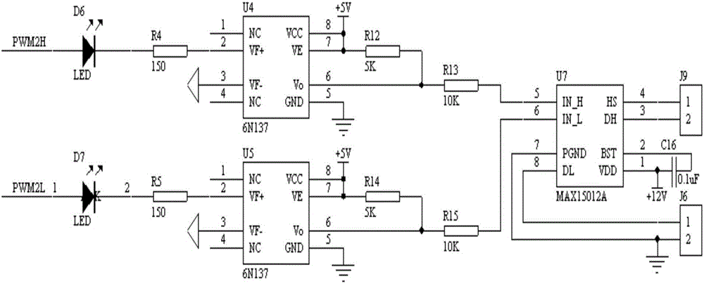
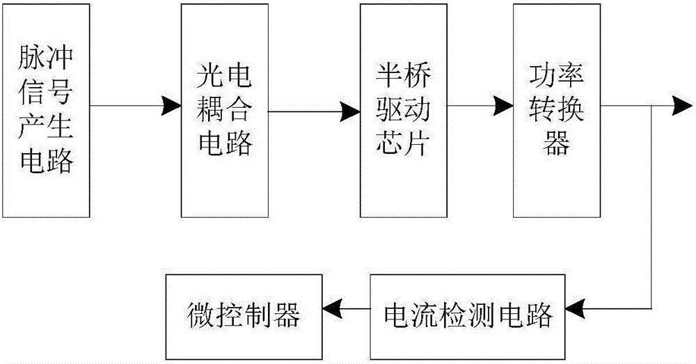
[0036] like figure 2 As shown, the power converter drive circuit for electric vehicle charging piles of the present invention includes several independent pulse signal generation circuits, and the pulse signals output by each pulse signal generation circuit are respectively sent to the corresponding photoelectric coupling circuit for denoising , the denoised pulse signals are respectively sent to the half-bridge driver chip, and after being amplified and processed by the half-bridge driver chip, a driving signal for driving the power converter is generated. The power converter is also connected to a current detection circuit, and the current detection circuit is connected to a microcontroller. The current detection circuit detects the current signal output by the power converter, and transmits the detected current signal to the microcontroller; when the detected current sign...


PUM


Abstract

The invention discloses a drive circuit and method of a power converter as well as an electric vehicle charging pile. The drive circuit comprises a control unit and a half-bridge drive unit, wherein the control unit is used for generating a drive signal and transmitting the generated drive signal to the half-bridge drive unit through an optical coupler isolation unit, and the half-bridge drive unit drives a switch unit on a corresponding bridge arm to act to control the working state of the power converter. Compared with an existing drive circuit of the power converter of the charging pile, the drive circuit has the advantages that the electromagnetic compatibility level of the charging pile can be increased, on one hand, electromagnetic interference of the circuit to the surroundings is reduced, and on the other hand, the anti-interference capacity of the drive circuit is improved.

Description

technical field [0001] The invention relates to the field of electric vehicles, in particular to a power converter drive circuit, a method and a charging pile for electric vehicles. Background technique [0002] In order to reduce greenhouse gas emissions and dependence on oil imports, and vigorously promote the development of clean energy, the State Grid Corporation of China coordinated the construction of charging and swapping facilities and interconnection, and built a total of 2,300 smart substations, 1,537 charging and swapping stations, and 29,600 charging piles across the country. indivual. [0003] At present, there are mainly six-pulse rectification, twelve-pulse rectification, PWM, LLC and other chargers. Among them, PWM rectification chargers often use a three-phase VSR topology, that is, a three-phase half-bridge structure. How to quickly and effectively charge and replace electric vehicles, improve the driving capacity of charging piles, reduce the volume of ch...

Claims


Application Information

Patent Timeline
Patent Type & Authority Applications(China)
IPC IPC(8): H02M1/44
CPCH02M1/44H02M1/0054
Inventor 王建陈玉峰朱文兵姚金霞辜超彭飞李杰朱庆东朱孟兆杜修明周加斌朱振华白德盟马艳任敬国袁海燕张振军
Owner ELECTRIC POWER RESEARCH INSTITUTE OF STATE GRID SHANDONG ELECTRIC POWER COMPANY
Why Eureka
Try Eureka