Direct feature control-based novel salient-pole permanent magnet synchronous motor control method

A permanent magnet synchronous motor, feature control technology, applied in the control of generators, motor generator control, control of electromechanical brakes, etc., can solve problems such as difficult parameter adjustment

Active Publication Date: 2016-08-17
同实(山西)工业技术有限公司
View PDF3 Cites 7 Cited by
  • Summary
  • Abstract
  • Description
  • Claims
  • Application Information

AI Technical Summary

Problems solved by technology

[0004] The purpose of the present invention is to provide a new salient pole permanent magnet synchronous motor control method based on direct characteristic control, so that the motor can be controlled based on modern control theory in addition to traditional vector control, not only can quickly improve the response speed, It can also avoid a series of problems such as difficulty in parameter adjustment caused by the use of PI in multiple places in traditional control

Method used


Image

  • Direct feature control-based novel salient-pole permanent magnet synchronous motor control method
  • Direct feature control-based novel salient-pole permanent magnet synchronous motor control method
  • Direct feature control-based novel salient-pole permanent magnet synchronous motor control method

Examples


Embodiment Construction

[0060] The present invention will be further explained below with reference to the drawings and examples.

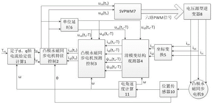
[0061] figure 1 It is a block diagram of the overall structure of a salient pole permanent magnet synchronous motor electric vehicle system based on feature control. The system includes the calculation of stator d and q axis current setpoints 1, the salient pole permanent magnet synchronous motor feature control 2, and the salient pole permanent magnet synchronous motor prediction Control 3. Sliding mode variable structure observer 4. Coordinate transformation 5. Unit delay module 6. SVPWM module 7. Voltage source inverter 8. Salient pole permanent magnet synchronous motor 9. Position sensor 10. Electrical angular velocity calculation module 11. .

[0062] The input terminal of the position sensor 10 is drawn from the output terminal of the salient-pole permanent magnet synchronous motor 9, and the input terminal of the electrical angular velocity calculation module 11 is d...


PUM


Abstract

The invention provides a direct feature control-based novel salient-pole permanent magnet synchronous motor control method, which comprises the following links: (1) determining a voltage equation of an alpha axis and a beta axis of a salient-pole permanent magnet synchronous motor under a static coordinate system; (2) with currents of the alpha axis and the beta axis of a stator and flux linkages of the alpha axis and the beta axis of a rotor as state variables, listing a corresponding state equation observer according to the voltage equation in the step (1); (3) designing a sliding mode variable structure observer according to the step (2) and observing the currents of the alpha axis and the beta axis of the stator and the flux linkages of the alpha axis and the beta axis of the rotor in a current state; (4) carrying out discretization according to the state equation in the step (2) and obtaining a prediction control equation, namely predicting the currents of the alpha axis and the beta axis of the stator and the flux linkages of the alpha axis and the beta axis of the rotor at the next moment; and (5) determining voltages of the alpha axis and the beta axis of the stator by the predicted currents of the alpha axis and the beta axis of the stator and the currents, of d axis and q axis of the stator, calculated by a given torque and feeding the voltages to an SVPWM. The direct feature control-based novel salient-pole permanent magnet synchronous motor control method can be widely applied to the field of electric automobiles.

Description

Technical field [0001] The invention relates to a control method of a novel salient pole permanent magnet synchronous motor based on direct feature control, which is suitable for electric vehicle systems and other fields where AC motors, especially salient pole permanent magnet synchronous motors, are the control core. Background technique [0002] At present, in the fields of electric vehicle systems, most of the control strategies used for salient-pole permanent magnet synchronous motors are still based on vector control. The core of vector control is the dual-loop structure, that is, the outer speed loop and the inner current loop. It is inevitable to use PI regulators, but PI regulators also have some problems of their own, such as insufficient bandwidth, easy saturation and so on. In response to these problems, some restraining methods and means have been proposed, but the overall control method is undoubtedly making the system and structure more complicated. Therefore, in ...

Claims


Application Information

Patent Timeline
Patent Type & Authority Applications(China)
IPC IPC(8): H02P21/00H02P21/13H02P27/12
CPCH02P21/0007H02P21/13H02P27/12
Inventor 康劲松
Owner 同实(山西)工业技术有限公司
Why Eureka
Try Eureka