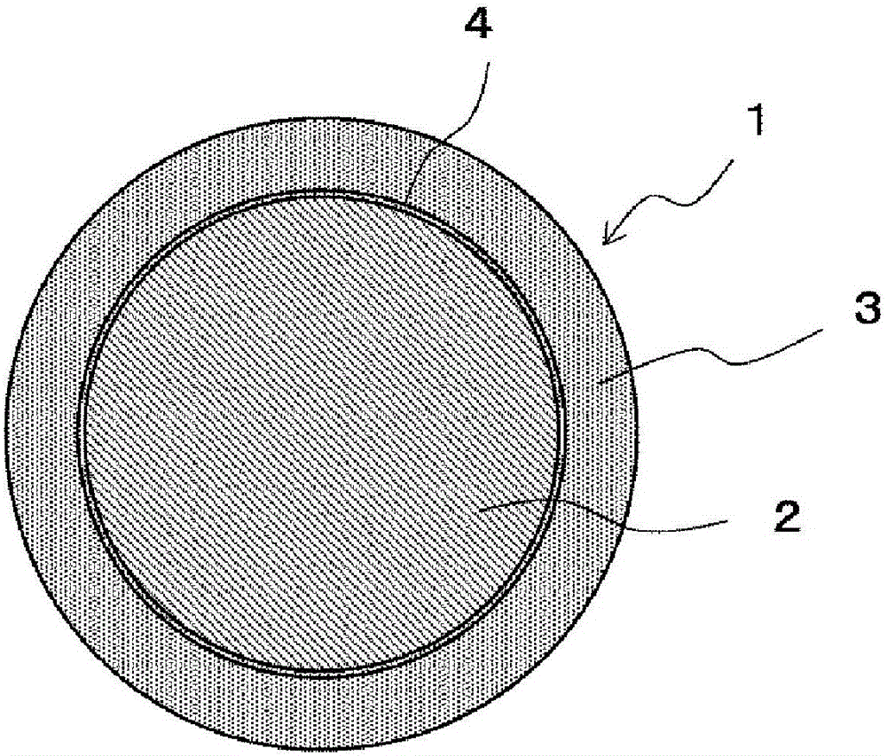
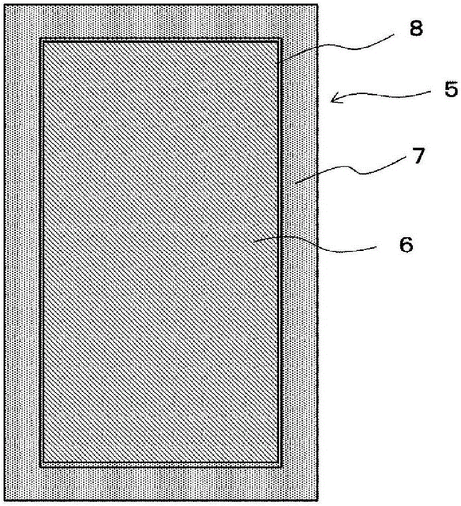
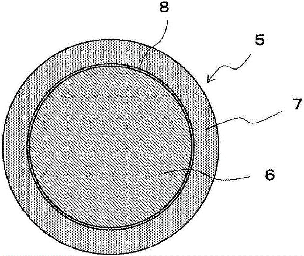
Cu core ball, solder paste, formed solder, cu core column, and solder joint
A technology of brazing joints and core balls, which is applied in the direction of welding equipment, welding media, welding/cutting media/materials, etc., and can solve problems such as connecting short circuits between electrodes
Active Publication Date: 2016-08-17
SENJU METAL IND CO LTD
View PDF11 Cites 9 Cited by
- Summary
- Abstract
- Description
- Claims
- Application Information
AI Technical Summary
Problems solved by technology
[0004] However, when BGA is applied to a semiconductor package mounted in three-dimensional high density, the solder balls are crushed due to the weight of the semiconductor package, and a connection short circuit occurs between electrodes.
This becomes an obstacle to high-density installation
Method used
View moreImage
Smart ImageViewing Examples
Examples
Embodiment
[0104] Hereinafter, examples of the Cu core ball 1 of the present invention will be described, but the present invention is not limited to these.
Login to View More PUM
| Property | Measurement | Unit |
|---|---|---|
| purity | aaaaa | aaaaa |
| diameter | aaaaa | aaaaa |
| purity | aaaaa | aaaaa |
Abstract
Provided are a Cu core ball and a Cu core column making it possible to obtain drop strength and strength in relation to heat cycle. The Cu core ball (1) is provided with: a Cu ball (2) configured from Cu or a Cu alloy; and a solder layer (3) configured from a solder alloy comprising Sn and Cu, the solder layer (3) covering the Cu ball (2). The solder layer (3) contains 0.1-3.0% Cu, the balance being Sn and unavoidable impurities.
Description
Technical field [0001] The present invention relates to Cu core balls formed by covering Cu balls with a solder alloy, solder paste using Cu core balls, formed solder using Cu core balls, brazing joints using Cu core balls, Cu core columns (column) and Brazing joints using Cu core posts. Background technique [0002] In recent years, due to the development of small information equipment, electronic components mounted there are rapidly miniaturizing. In accordance with the requirements for miniaturization of electronic components, in order to cope with the narrowing of connection terminals and the reduction of mounting area, a ball grid array package (hereinafter referred to as "BGA") with electrodes provided on the back surface is being applied. [0003] Among the electronic components using BGA, there is, for example, a semiconductor package. In the semiconductor package, a semiconductor chip having electrodes is sealed with resin. Solder bumps are formed on the electrodes of t...
Claims
Login to View More Application Information
Patent Timeline
 Patent Type & Authority Applications(China)
IPC IPC(8): B23K35/14B22F1/00B22F1/02B23K35/22B23K35/26C22C13/00H01L21/60C22F1/00C22F1/08B22F1/065B22F1/17
CPCB22F1/00B23K35/26B23K35/22C22C13/00C22C1/0483H01L24/13H01L2225/06517H01L2924/15311H01L2225/06513H01L2224/13411C25D3/60H01L23/556H01L24/81H01L2224/13294H01L2224/13347H01L2224/81075H01L2224/81211H01L2224/81395H01L2224/81444H01L2224/81447H01L2224/81815H01L2224/81048H01L2224/13455H01L2224/13457H01L2224/13311H01L2224/11825H01L2224/13561H01L24/05H01L24/11H01L24/16H05K3/3463H01L2224/0401H01L2224/05647H01L2224/13013H01L2224/13014H01L2224/13016H01L2224/13017H01L2224/13147H01L2224/13611H01L2224/13655H01L2224/13657H01L2224/16145H01L2224/16227H01L2224/81024H05K2201/0218H01L2224/13012C25D7/00H01L2924/351C23C28/021B23K35/0222B23K35/025B23K35/262B23K35/302C22C9/00B22F1/065B22F1/17H01L2924/013H01L2924/01029H01L2924/00014H01L2924/0105H01L2924/01051H01L2924/01083H01L2924/0103H01L2924/01026H01L2924/01013H01L2924/01033H01L2924/01047H01L2924/01049H01L2924/01048H01L2924/01028H01L2924/01082H01L2924/01044H01L2924/01015H01L2924/01016H01L2924/01092H01L2924/00012H01L2924/0109H01L2924/01203H01L2924/01204B23K35/0244
Inventor 服部贵洋相马大辅六本木贵弘佐藤勇
Owner SENJU METAL IND CO LTD
Features
- R&D
- Intellectual Property
- Life Sciences
- Materials
- Tech Scout
- Unparalleled Data Quality
- Higher Quality Content
- 60% Fewer Hallucinations
Learn More Browse by: Latest US Patents, China's latest patents, Technical Efficacy Thesaurus, Application Domain, Technology Topic, Popular Technical Reports.
© 2025 PatSnap. All rights reserved.Legal|Privacy policy|Modern Slavery Act Transparency Statement|Sitemap|About US| Contact US: help@patsnap.com


