A straw chopping and throwing test bench

A test bench and straw technology, applied to cutting equipment, agricultural machinery and tools, and packaging, can solve the problems of not being able to quickly and effectively complete the bundling operation, reduce the throwing accuracy of the bundling device, and affect the speed of bundling operations, etc. Achieve the effects of improving the throwing accuracy and bundling efficiency, reducing straw leakage and outside throwing, and good control

Inactive Publication Date: 2017-12-19
JILIN UNIV
View PDF5 Cites 0 Cited by
  • Summary
  • Abstract
  • Description
  • Claims
  • Application Information

AI Technical Summary

Problems solved by technology

[0003] However, for the side traction small square baler used in the bundling operation of corn, reed and other whole straw, because the corn straw is thick and hard, the small square baled straw is cut for a long time, resulting in low baling density and serious damage to the spring teeth. , poor machine reliability, low operating efficiency, less application
In response to this situation, the pick-up mechanism was improved, using a hammer-type pick-up structure, which can chop up and pick up the whole straw, and increase the bundling density. Part of the straw cannot be accurately thrown into the bundling room of the baler at one time, and the straw will fall back and be cut for the second time, causing unnecessary energy consumption and reducing the throwing accuracy of the bundling device, and the bundling operation cannot be completed quickly and effectively, which affects the Baling speed

Method used


Image

  • A straw chopping and throwing test bench
  • A straw chopping and throwing test bench
  • A straw chopping and throwing test bench

Examples


Embodiment Construction

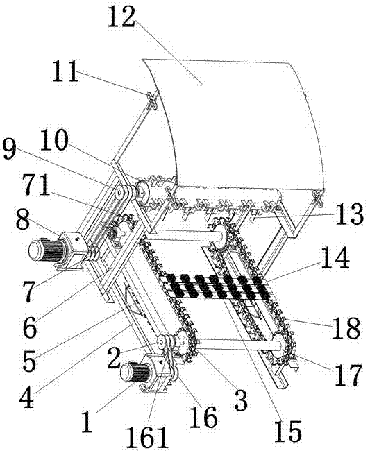
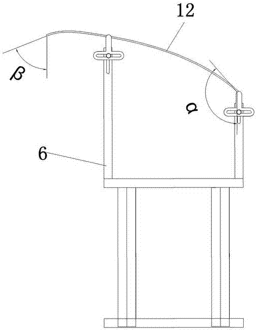
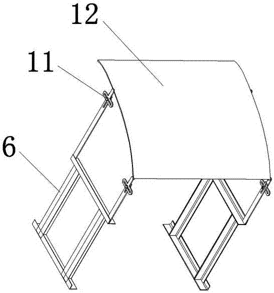
[0034] Such as figure 1 As shown, the present invention includes a first motor 1, a first pulley 2, a conveyor belt 3, a conveyor belt bracket 4, a lifting device 5, a roller bracket 6, a second pulley 7, a second motor 8, a third belt Wheel 9, idler roller 10, T-shaped connector 11, material baffle plate 12, blade 13, chain plate 14, support brush 15 and fourth pulley 16, the first motor 1 passes through the fourth pulley 16 and the first belt 161 is connected with the first pulley 2, the first pulley 2 is installed on the bearing 19 of the conveyor belt 3, and the first motor 1 provides conveying power for the conveyor belt 3;

[0035] Such as Figure 6 As shown, the conveyor belt 3 is composed of a sprocket 17, a chain 18, a bearing 19 and a bearing seat 20; the sprocket 17 is arranged on the bearing seat 20 through the bearing 19, the bearing seat 20 is arranged on the conveyor belt bracket 4, and the chain 18 is wound around On the sprocket 17, chain plates 14 are set o...


PUM


Abstract

The invention discloses a straw chopping and throwing test stand. A conveyer belt bracket of the straw chopping and throwing test stand is provided with a lifting device, and the lifting device can be used for lifting a conveyer belt so as to adjust the distance between straw and a blade; a conveyer belt chain plate is provided with a support hair brush; when being transmitted, the straw is put on the support hair brush, so that the chain plate is prevented from being mistakenly cut by the blade when the blade is used for cutting the straw; a feeding angle and a cavity-entry angle of a material baffle for blocking the straw are adjustable; the optimal feeding angle and cavity-entry angle of the baffle are designed for the straw with different masses, water contents and radii; the baffle is designed to have a smooth curved surface, thus being helpful to enable the straw to be guided into a chamber accurately and rapidly; a carrier roller is connected with a motor, so that the rotating speed of the blade can be adjusted; the conveyer belt is connected with the motor, so that the conveying speed of the conveyer belt can be adjusted. After the straw chopping and throwing test stand is adopted, different blades can be replaced for tests; the straw chopping and throwing test stand effectively improves throwing accuracy, also can solve the problem of short service life of the material baffle, reduces the phenomena of missed throwing and outward throwing, and is less in experimental energy consumption.

Description

technical field [0001] The invention belongs to the technical field of agricultural machinery, and in particular relates to a straw chopping and throwing test bench. Background technique [0002] Straw, as a sufficient renewable new energy, has a huge amount of reserves in my country every year. Every year, the straw produced in Northeast my country alone reaches nearly 100 million tons and continues to grow. Straw can not only store water and moisture, raise livestock, biogas fermentation and papermaking , and plays an irreplaceable role in combustion power generation and as building materials; the straw scattered in the field needs to be bundled to facilitate the comprehensive application of papermaking and power generation. There are many types of straw balers used in the market . [0003] However, for the side traction small square baler used in the bundling operation of corn, reed and other whole straw, because the corn straw is thick and hard, the small square baled str...

Claims


Application Information

Patent Timeline
Patent Type & Authority Patents(China)
IPC IPC(8): A01F29/06A01F29/09A01F15/10
CPCA01F15/10A01F29/06A01F29/09A01F29/095
Inventor 贾洪雷王佳旭袁洪方陈玉龙郭明卓赵佳乐郭慧庄健齐江涛丛永健刘慧力
Owner JILIN UNIV
Why Eureka
Try Eureka