Fabricated beam-column bolt joint connection device with cover plate and double flanges

A technology of double-flange beam-column and bolt joints, which can be used in protective buildings/shelters, building components, earthquake-proof and other directions, and can solve the problems of poor joint ductility, difficult rigid connection, and large residual stress.

Active Publication Date: 2016-08-24
BEIJING UNIV OF TECH
View PDF5 Cites 26 Cited by
  • Summary
  • Abstract
  • Description
  • Claims
  • Application Information

AI Technical Summary

Problems solved by technology

[0003] The beam-column joint is the most important joint in the fabricated steel structure system, which directly affects the construction speed and the degree of assembly of the structure. Therefore, the beam-column joints should be connected with high-strength bolts that are easy to operate as much as possible, and the bolts should be arranged as far as possible. It is easy for workers to fasten on site. The beam-column joints used in the existing engineering examples have the following disadvantages: In the traditional beam-column fully welded joints, the upper and lower flanges of the beam and the web and the column are welded on site. Although this connection method is a rigid connection, However, the ductility of the joints is poor, brittle failure is prone to occur in earthquakes, and on-site welding is required, which greatly affects the construction speed and quality. It is not used in multi-story fabricated steel structures. At the same time, due to the large welding area, it is easy to generate large residual stress , affecting the mechanical performance of the node
In the traditional bolted and welded joint connection, the upper and lower flanges of the beam end are welded to the column on site, and the web at the beam end is bolted to the column through a shear plate. This connection method requires on-site welding, which greatly affects the construction speed and quality, and the construction The program is complex and it is not easy to achieve rigid connection

Method used


Image

  • Fabricated beam-column bolt joint connection device with cover plate and double flanges
  • Fabricated beam-column bolt joint connection device with cover plate and double flanges
  • Fabricated beam-column bolt joint connection device with cover plate and double flanges

Examples


Embodiment Construction

[0022] The specific connection mode of the beam-column node of the present invention will be described in detail below in conjunction with the accompanying drawings.

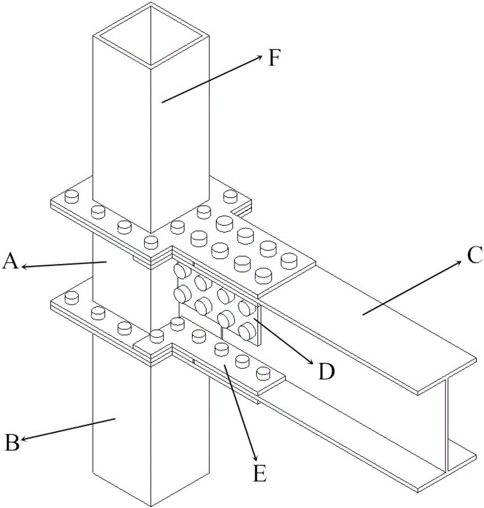
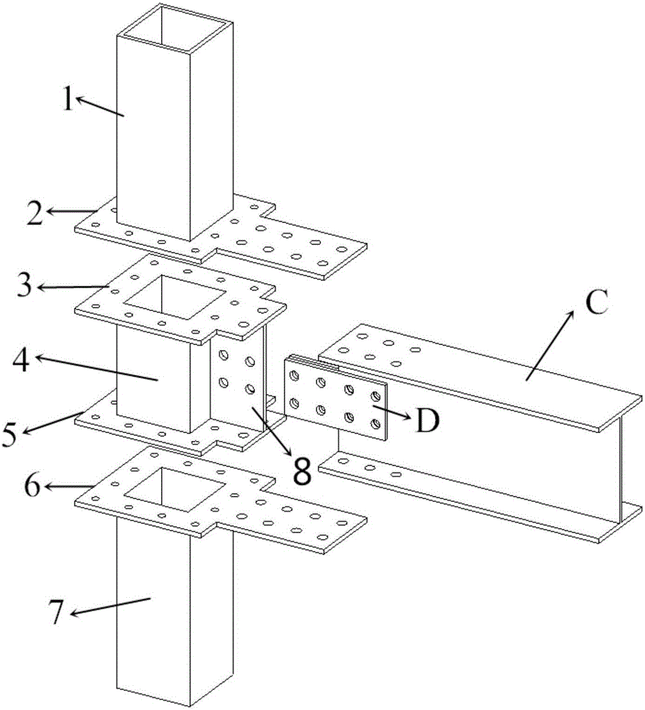
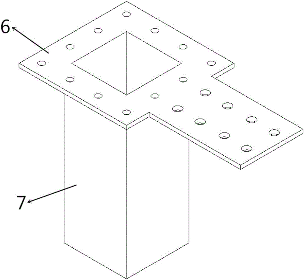
[0023] as attached Figure 1-7 As shown, the first flange (2) of the node is welded to the lower end of the first square steel pipe column (1) to form the upper column F; the second flange (6) of the node is welded to the second steel pipe column ( 7) The upper end forms the lower column B; the third flange (3), the fourth flange (5) and the shear plate (8) above and below the node column base are respectively welded to the third-party steel pipe column (4) according to the schematic diagram ) to form a column seat A; the beam C, the plate D, the splint E, the upper and lower column flanges, and the column seat flange are all prefabricated in the factory to dig holes, and the structures A and B, A and C, A and F is connected by splint E, patch D and single or multiple rows of bolts, and the size of the bolts de...


PUM


Abstract

The invention discloses a fabricated beam-column bolt joint connection device with a cover plate and double flanges, and belongs to the technical field of structural engineering. The fabricated beam-column bolt joint connection device comprises an upper column flange plate (2), an upper column square-steel tubular column (1), column base flange plates (3) and (5), a column base square-steel tubular column (4), a shear plate (8), a lower column flange plate (6), a lower column square-steel tubular column (7), an H-shaped steel beam C, an attaching plate D and a clamping plate E. The upper square-steel tubular column and the lower square-steel tubular column are welded to the flange plates integrally in a factory. A column base in the middle is formed by integral welding of the upper flange plate, the lower flange plate, the middle square-steel tubular column and the shear plate in the factory. The welded portions can be completed in the factory, bolts are adopted for on-site assembly and are fastened conveniently and quickly, construction speed and quality are increased greatly, and the fabricated beam-column bolt joint connection device is suitable for the development of fabricated steel structures. According to the fabricated beam-column bolt joint connection device, joints are semi-rigid, with high ductility and bearing capability; clamping plates are made from steel material with low strength, so that earthquake energy can be dissipated fully and post-earthquake restoration is facilitated.

Description

technical field [0001] The invention relates to an assembled double-flange beam-column bolt node connection device with a cover plate, which belongs to the technical field of structural engineering. Background technique [0002] At present, the systematic research on high-rise steel structure residences at home and abroad is in its infancy, and the innovation of industrially assembled high-rise steel structure systems is imperative. The prefabricated steel structure system refers to the building produced by manufacturing housing units or components according to uniform and standard building part specifications, and then transporting them to the construction site for assembly in place. It is characterized by light building weight, energy saving and environmental protection, fast construction speed, and high degree of industrialization. It can solve many problems such as the low level of construction industrialization in my country, low labor productivity in house construction...

Claims


Application Information

Patent Timeline
Patent Type & Authority Applications(China)
IPC IPC(8): E04B1/24E04B1/58E04B1/98E04H9/02
CPCE04B1/24E04B1/2403E04B2001/2406E04H9/021E04H9/024
Inventor 刘学春王鹤翔杨志炜
Owner BEIJING UNIV OF TECH
Why Eureka
Try Eureka