
A Novel AGC Control Method for Circulating Fluidized Bed Boiler

A technology of circulating fluidized bed and control method, which is applied in the directions of fluidized bed combustion equipment, combustion method, and fuel burned in a melted state, etc., can solve the problem of accelerated equipment loss, frequent fluctuation of control system performance in production process, and non-stationary random signal disturbance. and other problems to achieve the effect of reducing lag

Active Publication Date: 2017-11-03
SOUTHEAST UNIV
View PDF6 Cites 0 Cited by
  • Summary
  • Abstract
  • Description
  • Claims
  • Application Information

AI Technical Summary

Problems solved by technology

At the same time, for the units connected to the grid, the power grid often has precise and strict requirements on the load of the units. As far as the technical requirements of the power grid in my country are concerned, the rate of lifting and lowering the load of the unit during AGC joint debugging should reach more than 2.0MW / min, and The load steady-state control accuracy is within ±0.5% Pe, and the maximum load dynamic control accuracy is within ±1.5% Pe, that is, the unit often needs to complete a large-scale load tracking in a short period of time. The traditional fluidized bed boiler is due to the boiler side The delay and large inertia, the AGC load lifting rate and accuracy are often not well guaranteed, so the new situation also puts forward new requirements for the AGC control structure of the unit
[0004] In addition, with the increasing size and complexity of industrial systems, a large number of complex time-varying disturbances containing non-stationary random signals have an increasingly serious impact on the normal operation of the control system
The decline in the performance of the control system will further cause frequent fluctuations in the production process, which will not only directly affect the quality of the product and the safe operation of the system, but also lead to accelerated wear and tear of equipment.

Method used


Image

  • A Novel AGC Control Method for Circulating Fluidized Bed Boiler
  • A Novel AGC Control Method for Circulating Fluidized Bed Boiler
  • A Novel AGC Control Method for Circulating Fluidized Bed Boiler

Examples


Embodiment Construction

[0084] The technical solution of the present invention will be further introduced below in combination with specific embodiments.

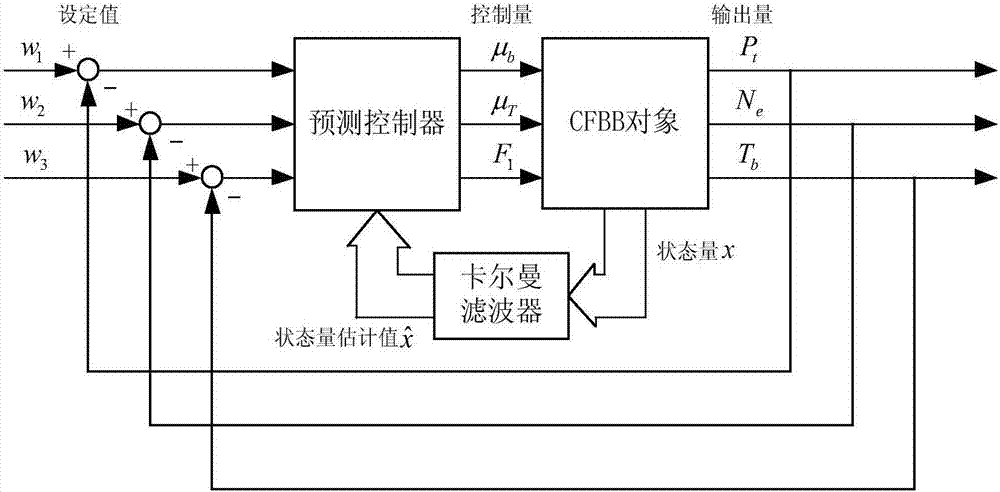
[0085] The CFB boiler control object model involved in this example is obtained by system identification based on relevant test data of a certain power plant. In order to illustrate the advantages of the new AGC control structure, in this example, two sets of different control object transfer function models are obtained by identifying the data related to the 75% load condition, which are the 2×2 transfer function model based on the traditional 2×2 AGC control structure and the The 3×3 transfer function model based on the new 3×3 AGC control structure; the predictive control algorithm based on the state space model obtains the corresponding dynamic parameter matrix through the step response test of the object.

[0086]

[0087] Below, this example is based on two different transfer function models for simulation verification. For the transfer ...


PUM


Abstract

The invention discloses a novel AGC control method of a circulating fluidized bed boiler. The novel AGC control method comprises the following steps that S1, the step response coefficient of a controlled object is acquired; S2, the state space approximate expression form of the controlled object is acquired; S3, a prediction model of predictive control is acquired; S4, rolling optimization of the control method is carried out; and S5, feedback compensation of the control method is carried out. According to the method, the dynamic adjustment function of primary air on the boiler side on the unit power of the steam engine side in the dynamic process of the circulating fluidized bed boiler is fully utilized, hearth bed materials are fully utilized for energy storage, the lagged effect of the boiler fuel amount is reduced, and the disturbance suppression capacity of a system can be improved through an improved predictive control algorithm.

Description

technical field [0001] The invention relates to the research field of AGC control of a circulating fluidized bed, in particular to a novel AGC control method of a circulating fluidized bed boiler. Background technique [0002] Energy is the foundation of national economic development, and coal resources occupy a very important position in my country's primary energy structure, and its proportion is about 70%. On the other hand, the development and utilization of coal will produce a large amount of carbon dioxide, sulfur dioxide and Nitrogen oxides, thus causing serious environmental problems, in this context, the development of clean coal technology is imperative. Compared with other clean coal technologies, circulating fluidized bed technology is a more suitable choice in terms of technical completeness and economic applicability, both in line with my country's current national conditions. [0003] As a new type of coal combustion technology, circulating fluidized bed boile...

Claims


Application Information

Patent Timeline
Patent Type & Authority Patents(China)
IPC IPC(8): F23C10/28
CPCF23C10/28F23C2206/10
Inventor 陆琳辉李益国沈炯刘西陲吴啸潘蕾
Owner SOUTHEAST UNIV
Learn More