Eureka AIR delivers breakthrough ideas for toughest innovation challenges, trusted by R&D personnel around the world.

Nozzle and manufacturing method thereof

A manufacturing method and channel technology, applied in the combustion method, burner, combustion type and other directions, can solve the problems of limited service life of the burner, the flame shape cannot be effectively controlled, and the structure is complex, and achieves the reduction of the amount of iron oxide scale in the billet forging, comprehensive Good combustion performance and the effect of overcoming excessive local temperature

Active Publication Date: 2016-08-24
MAANSHAN TIANZHOU ENERGY SAVING ENG TECH
View PDF9 Cites 2 Cited by
  • Summary
  • Abstract
  • Description
  • Claims
  • Application Information

AI Technical Summary

Problems solved by technology

But, after actually using the burner of this application, it is found that the burner of this application also has the following defects that are difficult to overcome: (1) in this application, although the circumferential distribution structure of the natural gas channel is conducive to the mixing of natural gas and combustion-supporting air , but the burner in this application is a non-premixed gas burner, and the mixing of natural gas and combustion-supporting air is still unsatisfactory during combustion; Although the slender natural gas channel in the brick body disperses the natural gas and has the effect of refining and diverting the natural gas, it is found that the slender natural gas channel is prone to blockage during actual use, which seriously affects the smooth flow of production; (3) the When the burner of the application is in use, the shape of the flame cannot be effectively controlled, which often makes the temperature near the burner higher, resulting in a limited service life of the burner
However, the burner of this application still has the following disadvantages in actual use: the shape of the flame is difficult to keep stable during the combustion of natural gas, so that the temperature field in the furnace is difficult to stabilize, and cannot meet the occasions with high heating requirements.
The above-mentioned technical solutions are aimed at improving the structure of the burner, all of which are based on improving the mixing of fuel and air. The structure is relatively complicated, and it is inconvenient to maintain and manufacture. In addition, further improvement is still needed on the regulation of flame temperature, length, and combustion range.

Method used


Image

  • Nozzle and manufacturing method thereof
  • Nozzle and manufacturing method thereof
  • Nozzle and manufacturing method thereof

Examples


Embodiment 1

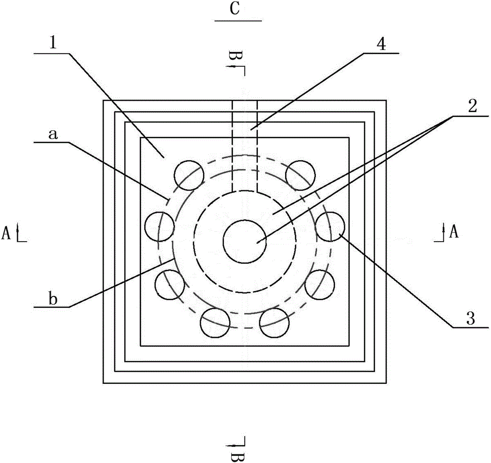
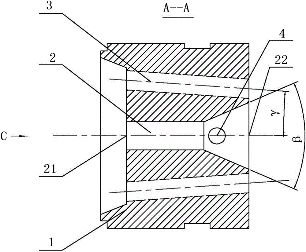
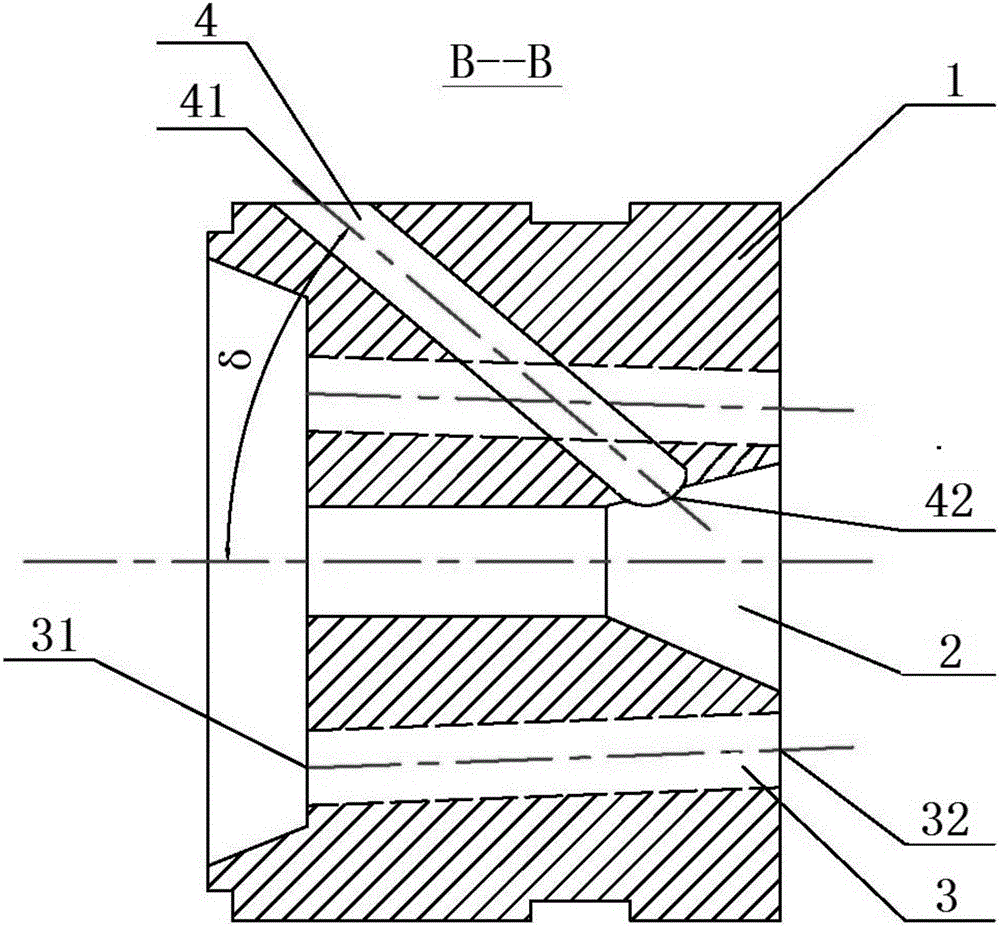
[0036] combine Figure 1~3 ( figure 1 for figure 2The view along the C direction), the burner of this embodiment includes a burner body 1 and a primary air channel 2, a secondary air channel 3 and a natural gas channel 4 located in the burner body 1, and the primary air channel 2 starts from the primary air The direction from the inlet 21 to the primary air outlet 22 is an equal cross-section channel section and a gradually widening channel section (specifically, the gradually widening channel section is a bell mouth hollow structure), and there are at least three secondary air channels 3 distributed around the circumference of the primary air channel 2 ( Three or more secondary air passages 3 have the effect of refining and splitting the secondary air), and the natural gas outlet 42 of the natural gas passage 4 communicates with the gradually widening passage section. Wherein, the included angle between the natural gas channel 4 and the central axis of the above-mentioned ...

Embodiment 2

[0050] The structure of the burner of this embodiment is basically the same as that of Embodiment 1, except that three secondary air passages 3 are distributed along the left middle, right middle and lower middle sides of the primary air passage 2, and three The included angle between the secondary air channel 3 and the central axis of the equal-section channel section is 4°, the included angle between the natural gas channel 4 and the central axis of the equal-section channel section is 35°, and the two sides on the axial section of the gradually widening channel section The included angle is 40°. The pipe diameter of the channel section with constant cross section is The pipe diameter of the secondary air channel 3 is The pipe diameter of natural gas channel 4 is

Embodiment 3

[0052] The burner of this embodiment, its structure is basically the same as that of Embodiment 1, the difference is that: four secondary air passages 3 are symmetrically distributed on the four sides of the primary air passage 2; four secondary air passages 3 and The angle between the central axis of the channel section with constant cross section is 6°, the angle between the natural gas channel 4 and the central axis of the channel section with equal cross section is 45°, and the angle between the two sides on the axial section of the gradually widening channel section is 50° . The pipe diameter of the channel section with constant cross section is The pipe diameter of the secondary air channel 3 is The pipe diameter of natural gas channel 4 is


PUM


Abstract

The invention discloses a nozzle and a manufacturing method thereof and belongs to the technical field of premixed gas burners. The nozzle comprises a primary air channel, secondary air channels and a natural gas channel which are located inside a nozzle body, the primary air channel comprises a uniform-section channel section and a gradually-wide channel section in sequence from a primary air inlet to a primary air outlet, three or more secondary air channels are distributed around the primary air channel, and a natural gas outlet of the natural gas channel is communicated with the gradually-wide channel section; the included angle delta between the natural gas channel and the central axis of the uniform-section channel section is greater than or equal to 30 degrees and less than or equal to 50 degrees; the included angle beta between two side edges on the axial cross section of the gradually-wide channel section is greater than or equal to 34 degrees and less than or equal to 60 degrees; the included angle gamma between each secondary air channel and the central axis of the uniform-section channel section is greater than or equal to 0 degree and less than or equal to 10 degrees. The nozzle is good in comprehensive combustion performance and used for gas combustion.

Description

technical field [0001] The invention belongs to the technical field of premixed gas burners, and more specifically relates to a burner and a manufacturing method thereof, especially suitable for regenerative burner systems. Background technique [0002] The regenerative high-temperature air combustion technology called HTAC (High Temperature Air Combustion) abroad is a new concept of combustion technology proposed by foreign countries in the last century. This technology organically combines flue gas waste heat recovery with high-efficiency combustion and low NOx technologies. It preheats the combustion-supporting air from room temperature to a high temperature of 800-1000°C through high-efficiency heat storage materials, thereby achieving extreme energy saving and extreme reduction of NOx Emissions serve a dual purpose. [0003] Although regenerative high-temperature combustion technology is an energy-saving, environmentally friendly high-tech. However, domestic natural g...

Claims


Application Information

Patent Timeline
Patent Type & Authority Applications(China)
IPC IPC(8): F23D14/48F23D14/66F23D14/02F23D14/62
CPCF23D14/02F23D14/48F23D14/62F23D14/66F23D2203/007Y02E20/34
Inventor 许诗双陈光张西和廖为娟
Owner MAANSHAN TIANZHOU ENERGY SAVING ENG TECH
Why Eureka
Eureka Blog
Learn More