
Gas-liquid whole-heat exchange device with built-in cold and heat source based on metal fiberfill

A technology of metal fiber and total heat exchange, which is applied in household heating, household heating, heating methods, etc., can solve the problem of insufficient heat transfer coefficient of gas-liquid effective contact area, constrained internal cooling (heat) type dehumidification (regeneration) device Development and other issues

Active Publication Date: 2016-08-24
BEIJING KANGFU TECH
View PDF8 Cites 3 Cited by
  • Summary
  • Abstract
  • Description
  • Claims
  • Application Information

AI Technical Summary

Problems solved by technology

[0005] Related literature has reported that the internal cooling (heat) type dehumidification (regeneration) device uses plastic products and metal plates with good thermal conductivity to make the heat exchange coil of the dehumidification / regeneration device, but the effective contact area between gas and liquid and cold water (heat) There are deficiencies in the heat transfer coefficient between water) and the solution, and these deficiencies restrict the development of internal cooling (heat) dehumidification (regeneration) devices

Method used


Image

  • Gas-liquid whole-heat exchange device with built-in cold and heat source based on metal fiberfill
  • Gas-liquid whole-heat exchange device with built-in cold and heat source based on metal fiberfill
  • Gas-liquid whole-heat exchange device with built-in cold and heat source based on metal fiberfill

Examples


Embodiment Construction

[0026] The technical solution of the present invention will be further described below in conjunction with the accompanying drawings. In the following description, more details are set forth in order to fully understand the present invention, but the present invention can obviously be implemented in a variety of other ways different from this description, Those skilled in the art can make similar promotions and deductions based on actual applications without violating the connotation of the present invention, so the content of this specific embodiment should not limit the protection scope of the present invention.

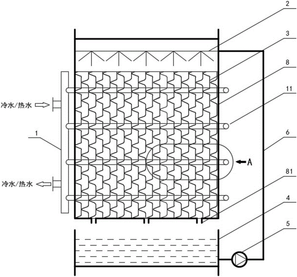
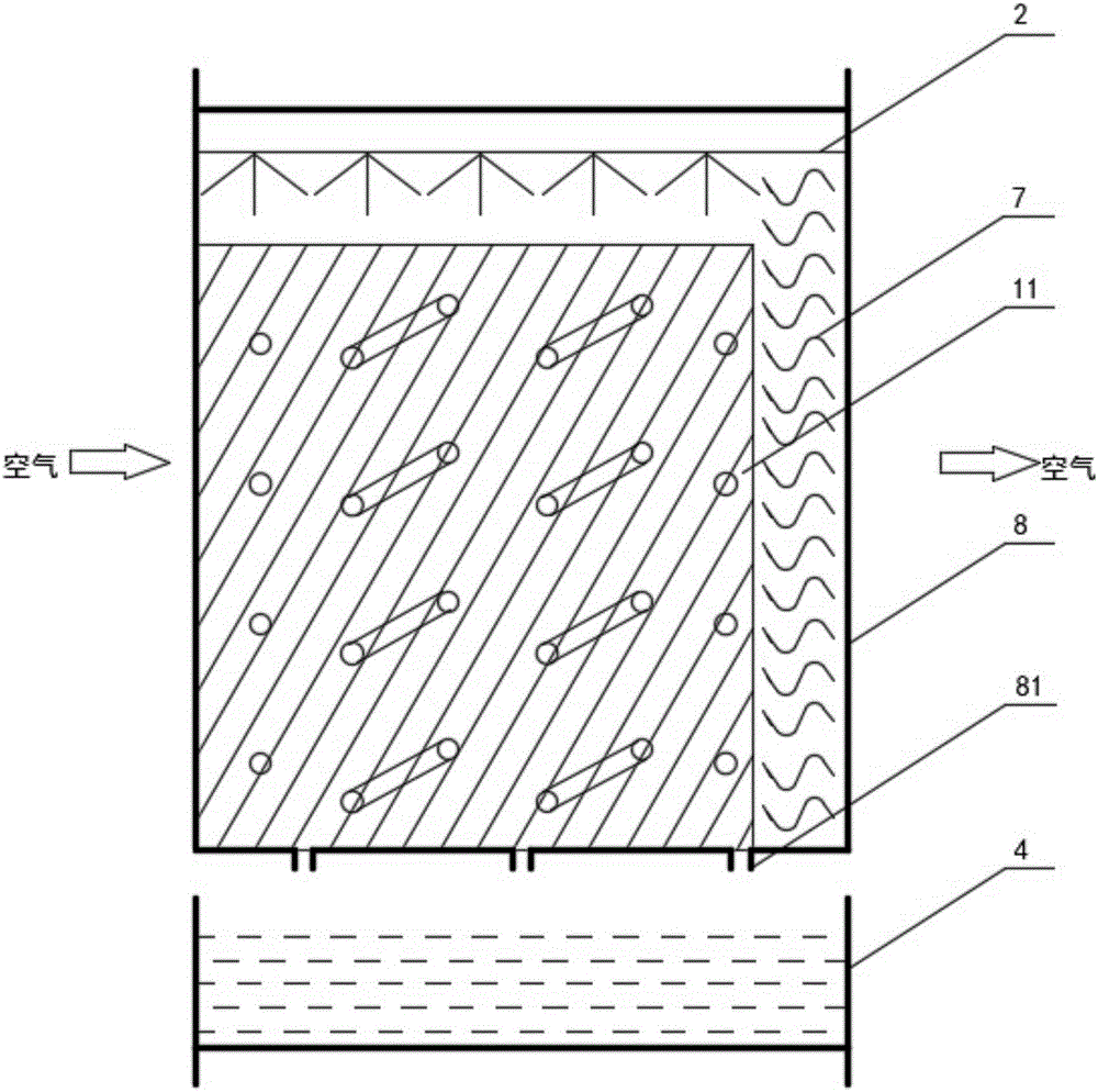
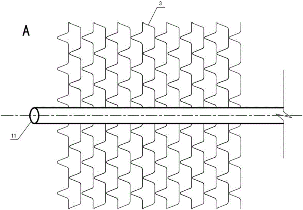
[0027] figure 1 and figure 2 It is a structural diagram of a gas-liquid total heat exchange device with a built-in cold and heat source based on metal fiber filler. The device mainly includes: heat exchange coil 1, sprayer 2, metal fiber filler 3, solution tank 4, solution pump 5, solution The circulation pipeline 6, the air outlet liquid shield 7 and the box bod...


PUM

PropertyMeasurementUnit
Peak heightaaaaaaaaaa

Abstract

The invention discloses a gas-liquid whole-heat exchange device with a built-in cold and heat source based on a metal fiberfill. The gas-liquid whole-heat exchange device comprises a heat exchange coil, a sprayer, a metal fiberfill, a solution tank, a solution pump, a solution circulating pipeline and a tank body, wherein the solution tank is located under the tank body; the sprayer is arranged above the metal fiberfill; the solution tank is communicated with the sprayer through the solution circulating pipeline; the solution pump is arranged on the solution circulating pipeline; the heat exchange coil and the metal fiberfill are arranged in the tank body; the metal fiberfill is formed by overlapping and assembling the inclined ripple metal fiber mats at two angles; the surfaces of the metal fiber mats are preferably treated through hydrophilic nano coating; the heat exchange coil comprises a metal heat exchange tube which penetrates through the metal fiber mats along the overlapped direction of the metal fiber mats; a solution flowing channel and an air-guide channel are formed between the two adjacent metal fiber mats. According to the device, can effectively increase the contact area between the solution and air can be effectively increased, the contact time of the solution and air can be effectively prolonged, the heat mass transfer coefficient can be increased and the device can be served as a dehumidifying or regenerating unit of a solution humidity-adjusting air-conditioning system.

Description

technical field [0001] The invention relates to the field of ventilation and air conditioning, in particular to a gas-liquid total heat exchange device with a built-in cold and heat source based on metal fiber filler used in a solution humidity control air conditioning system. Background technique [0002] In recent years, with the improvement of industrial production environment and process requirements, energy problems have become increasingly serious, and the demand for air-conditioning energy conservation has become increasingly urgent, making traditional air-conditioners face challenges in various aspects, and the air-conditioning system based on solution humidity control is a better solution way. [0003] Solution humidity control refers to the use of direct contact between air and hygroscopic salt solution for heat and moisture exchange to achieve the purpose of humidifying or dehumidifying the air. The surface vapor pressure of the hygroscopic solution directly affe...

Claims


Application Information

Patent Timeline
IPC IPC(8): F24F13/30F28C1/14F28F25/08
CPCF24F13/30F28C1/14F28F25/08
Inventor 敖顺荣马黎军
Owner BEIJING KANGFU TECH
Learn More