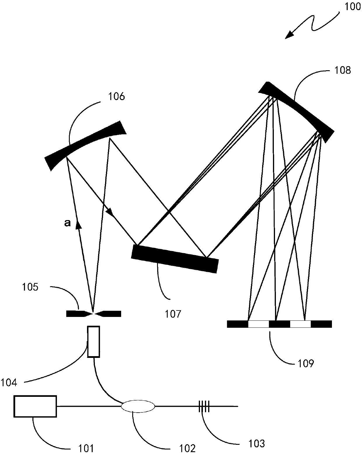
Fiber Bragg Grating Demodulation System Using Imaging Mirror to Improve Spectral Resolution
A technology of fiber grating demodulation and imaging mirror, which is applied in the direction of transmitting sensing components, converting sensor output, and measuring devices with optical devices, and can solve problems such as limited number of pixels and limited spectral spatial resolution
- Summary
- Abstract
- Description
- Claims
- Application Information
AI Technical Summary
Problems solved by technology
Method used
Image
Examples
Embodiment 1
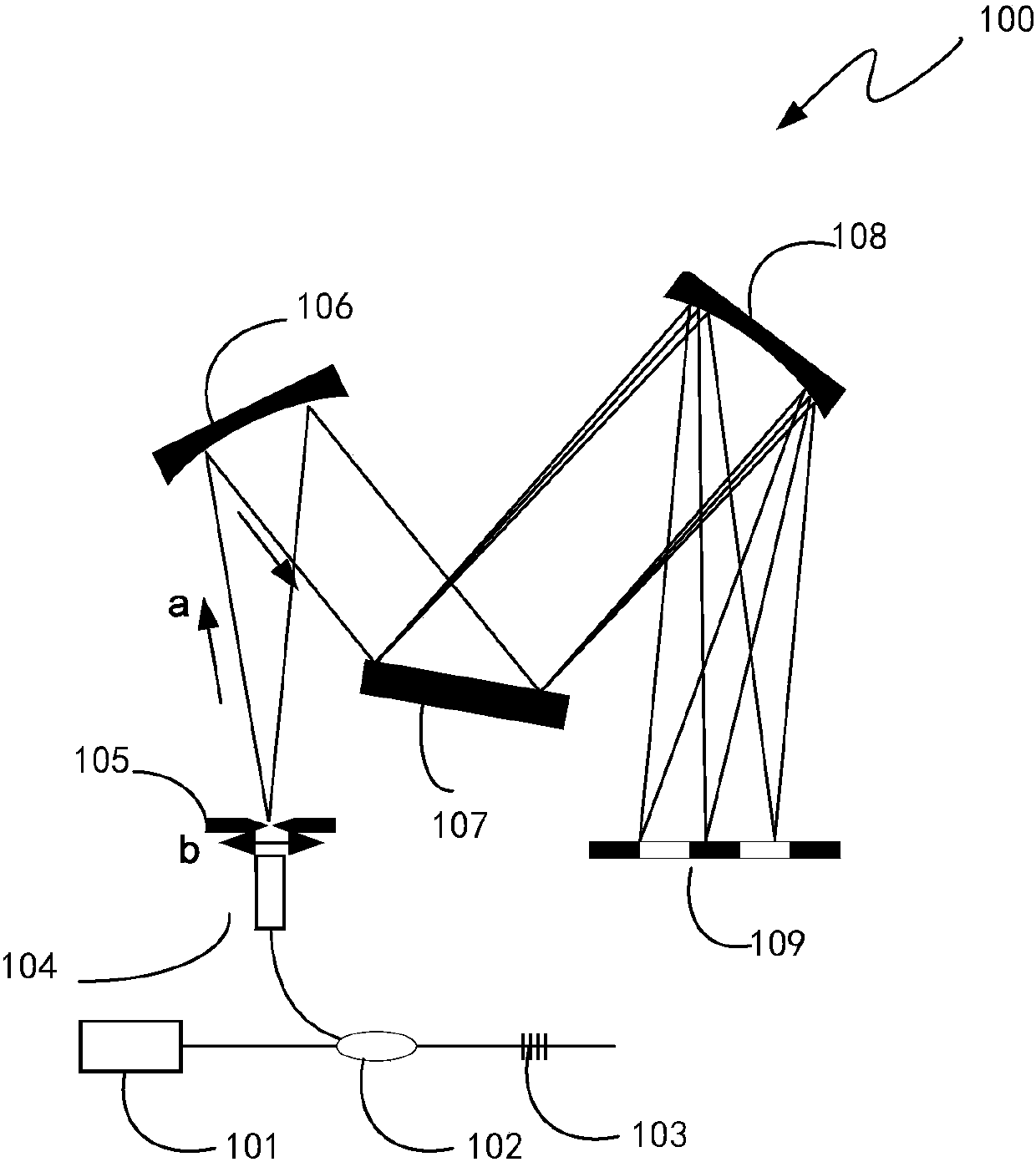
[0044] figure 2 A schematic diagram of the structure of a fiber grating demodulation system that uses slit translation to improve the spectral resolution of a line array image sensor is schematically shown. Such as figure 2 As shown, the slit 105 is adjusted so that the slit moves in the direction of the arrow b shown in the figure, the slit moving step is 0.1 micron, and the adjustment range is between 0-1 cm. The slit 105 is adjusted at high speed by a piezoelectric actuator. The piezoelectric actuator is controlled by a voltage control system, so that the spectral imaging position on the line image sensor can be moved within the minimum pixel interval. In this way, the light path incident on the imaging mirror 108 will change, and the fringes converged on the line array detector 109 will also change accordingly. By adjusting the width of the incident slit of the optical fiber, the slight movement of the stripes can be realized, thereby achieving the effect of improving...
Embodiment 2
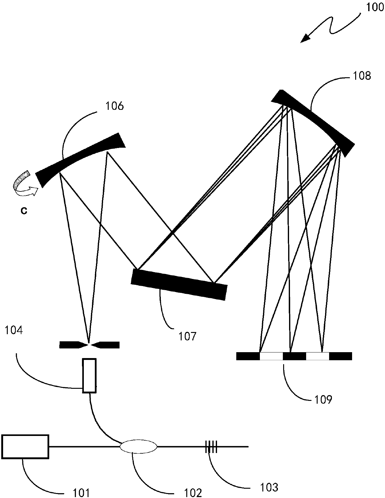
[0046] image 3 A schematic structural diagram of a fiber grating demodulation system that improves the spectral resolution of a detector array by fine-tuning a collimator mirror is schematically shown. Such as image 3 As shown, the collimating mirror 106 is adjusted so that the collimating mirror rotates in the direction of arrow c in the figure, and the rotation angle is 10°-30° counterclockwise or clockwise. The collimating mirror 106 is adjusted at high speed by piezoelectric actuators. The piezoelectric actuator is controlled by a voltage control system, so that the spectral imaging position on the line image sensor can be moved within the minimum pixel interval. In this way, the light path incident on the imaging mirror 108 will change, and the fringes converged on the line array detector 109 will also change accordingly. By adjusting the rotation angle of the collimating mirror, the slight movement of the stripes can be realized, thereby achieving the effect of impr...
Embodiment 3
[0048] Figure 4 A schematic structural diagram of a fiber grating demodulation system that uses a micro-movable grating to improve the spectral resolution of a detector array is schematically shown. Such as Figure 4 As shown, the spectroscopic grating 107 is adjusted so that the spectroscopic grating rotates in the direction of the arrow d in the figure, and the rotation angle is 10°-30° counterclockwise or clockwise. The split grating 107 is adjusted at high speed by piezoelectric actuators. The piezoelectric actuator is controlled by a voltage control system, so that the spectral imaging position on the line image sensor can be moved within the minimum pixel interval. In this way, the light path incident on the imaging mirror 108 will change, and the fringes converged on the line array detector 109 will also change accordingly. By adjusting the rotation angle of the spectroscopic grating, the slight movement of the fringe can be realized, thereby achieving the effect of...
PUM
 Abstract
Description
Claims
Application Information
 - R&D
- Intellectual Property
- Life Sciences
- Materials
- Tech Scout
- Unparalleled Data Quality
- Higher Quality Content
- 60% Fewer Hallucinations
Browse by: Latest US Patents, China's latest patents, Technical Efficacy Thesaurus, Application Domain, Technology Topic, Popular Technical Reports.
© 2025 PatSnap. All rights reserved.Legal|Privacy policy|Modern Slavery Act Transparency Statement|Sitemap|About US| Contact US: help@patsnap.com


