Deep-trough ore pulp sampler

A sampler and slurry technology, applied in the field of deep groove slurry sampler, can solve the problems of inaccurate data detection results, poor sample representativeness, inconvenient extraction, etc., and achieve good sample representativeness, high sampling efficiency, and convenient conversion of results Effect

Active Publication Date: 2016-08-24
YUNNAN HUALIAN ZINC & INDIUM
View PDF10 Cites 8 Cited by
  • Summary
  • Abstract
  • Description
  • Claims
  • Application Information

AI Technical Summary

Problems solved by technology

[0003] In view of the above situation and the detection needs of mineral processing technology, and to overcome the defects of the existing technology, the present invention provides a deep groove slurry sampler, which can effectively solve the inconvenience of sampling in the prior art, which has certain potential safety hazards, and the representativeness of the sample taken out is poor. Problems that lead to inaccurate data detection results

Method used


Image

  • Deep-trough ore pulp sampler

Examples


Embodiment 1

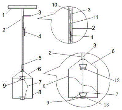
[0015] Embodiment 1: as figure 1 , a deep groove slurry sampler, which includes a handle 1, a hollow tube 2, a piston connecting rod 3, a tension spring 4, a piston connecting rod positioning block 5, a connecting body 6, a piston 7, a sampling cylinder 8 and a piston fixing block 9. The handle 1 is integrated with the hollow tube 2, the piston connecting rod positioning block 5, the connecting body 6, and the sampling cylinder 8. The piston connecting rod 3 is connected with the piston 7 and the piston positioning block 9. The upper end of the piston connecting rod 3 is connected from the middle The upper notch 10 on the side of the empty tube is pierced by 10 mm, the lower end of the tension spring 4 is fixed on the outer wall of the hollow tube 2, and the upper end is fixedly connected to the piston connecting rod 3 through the lower opening 11 on the side of the hollow tube 2, and the piston connecting rod 3 is connected to the piston rod 3. Rod positioning block 5 passes...

Embodiment 2

[0016] Embodiment 2: as figure 1 , a deep groove slurry sampler, which includes a handle 1, a hollow tube 2, a piston connecting rod 3, a tension spring 4, a piston connecting rod positioning block 5, a connecting body 6, a piston 7, a sampling cylinder 8 and a piston fixing block 9. The handle 1 is integrated with the hollow tube 2, the piston connecting rod positioning block 5, the connecting body 6, and the sampling cylinder 8. The piston connecting rod 3 is connected with the piston 7 and the piston positioning block 9. The upper end of the piston connecting rod 3 is connected from the middle The upper notch 10 on the side of the empty pipe passes through 8 mm, the lower end of the tension spring 4 is fixed on the outer wall of the hollow pipe 2, and the upper end is fixedly connected with the piston connecting rod 3 through the lower opening 11 on the side of the hollow pipe 2, and the piston connecting rod 3 is connected from the piston. Rod positioning block 5 passes t...

Embodiment 3

[0017] Embodiment 3: as figure 1 , a deep groove slurry sampler, which includes a handle 1, a hollow tube 2, a piston connecting rod 3, a tension spring 4, a piston connecting rod positioning block 5, a connecting body 6, a piston 7, a sampling cylinder 8 and a piston fixing block 9. The handle 1 is integrated with the hollow tube 2, the piston connecting rod positioning block 5, the connecting body 6, and the sampling cylinder 8. The piston connecting rod 3 is connected with the piston 7 and the piston positioning block 9. The upper end of the piston connecting rod 3 is connected from the middle The upper notch 10 on the side of the empty pipe is pierced by 12mm, the lower end of the tension spring 4 is fixed on the outer wall of the hollow pipe 2, and the upper end is fixedly connected with the piston connecting rod 3 through the lower opening 11 on the side of the hollow pipe 2, and the piston connecting rod 3 is connected to the piston from the piston. Rod positioning blo...


PUM


Abstract

The invention relates to a deep-trough ore pulp sampler. The deep-trough ore pulp sampler comprises a handle, a hollow pipe, a piston connecting rod, a tensioning spring, a piston-connecting-rod positioning block, a connecting body, a piston, a sampling barrel and a piston fixing block. The deep-trough ore pulp sampler is novel, unique, simple, convenient, rapid, and safe, flexible and reliable in operation and use, sampling working efficiency can be greatly improved, and the deep-trough ore pulp sampler is a great innovation in ore pulp samplers and ways; the problems that vertical positioning sampling in continuously-stirred ore pulp can not be achieved, consumed time is long, sample representativeness is poor, and potential safety hazards in sampling are large are effectively solved.

Description

technical field [0001] The invention relates to a sampler, in particular to a deep groove slurry sampler. Background technique [0002] With the continuous development of modern mining technology, mineral processing technology is changing with each passing day, but the development of its process sampling and testing equipment is lagging behind. The commonly used open manual samplers are mainly open samplers, which cannot be used for different pulp depths and pulps with specific pulp depths. Accurate sampling, due to the large sampling error, can not reflect the real problem, resulting in inaccurate data test results, can not effectively guide production, "Chinese Patent Publication No. CN203811420U, public date September 3, 2014, the name of the invention is a Conical tank slurry sampler, although this application discloses a conical sampler for sampling at different depths in flotation tanks, its disadvantage is that it lacks hard material to support the sampling vessel whe...

Claims


Application Information

Patent Timeline
Patent Type & Authority Applications(China)
IPC IPC(8): G01N1/14
Inventor 韦会福兰希雄
Owner YUNNAN HUALIAN ZINC & INDIUM
Why Eureka
Try Eureka