
Device and method for preparation of soil body for site soil body direct shear test and direct shear test

A technology for preparing devices and testing devices, which is applied in the preparation of test samples, measuring devices, and the use of stable shear force to test the strength of materials. It can solve the problems of large workload, high time and labor costs, geometric dimensions, Problems such as angle and flatness are not standard, so as to achieve the effect of convenient installation and disassembly, convenient transportation and avoiding errors

Active Publication Date: 2016-08-24
CHINA THREE GORGES UNIV
View PDF6 Cites 5 Cited by
  • Summary
  • Abstract
  • Description
  • Claims
  • Application Information

AI Technical Summary

Problems solved by technology

[0004] However, at present, there are two obvious difficulties in large-scale soil direct shear tests on site. One is the preparation of soil standard samples. The commonly used site soil direct shear test sample size is generally: length × width × height = 500mm×500mm×300mm
During the field test, a large sample soil (length, width, and height are all greater than 500mm) is generally excavated at the selected test site, and then the sample is manually prepared with tools such as a soil cutter, but the manually prepared sample The geometric dimensions, angles, and flatness are often not standard, and it is difficult to meet the requirements of the test specifications, which directly leads to the discreteness of the test results and affects the accuracy of the test results; on the other hand, it is the normal load application of the direct shear test. , usually using methods such as ground anchors and surcharges. However, the workload of burying ground anchors and applying surcharges is large, and the time and labor costs are high. Therefore, a more convenient method of applying normal loads is urgently needed

Method used


Image

  • Device and method for preparation of soil body for site soil body direct shear test and direct shear test
  • Device and method for preparation of soil body for site soil body direct shear test and direct shear test
  • Device and method for preparation of soil body for site soil body direct shear test and direct shear test

Examples


Embodiment Construction

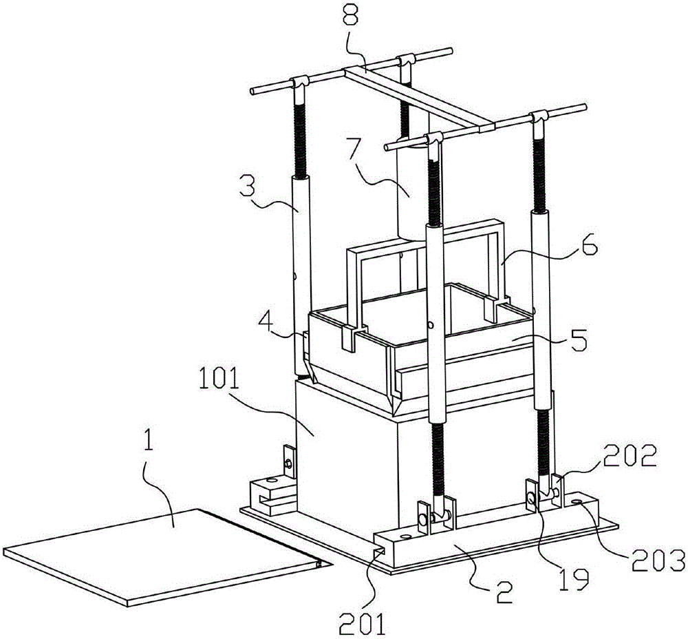
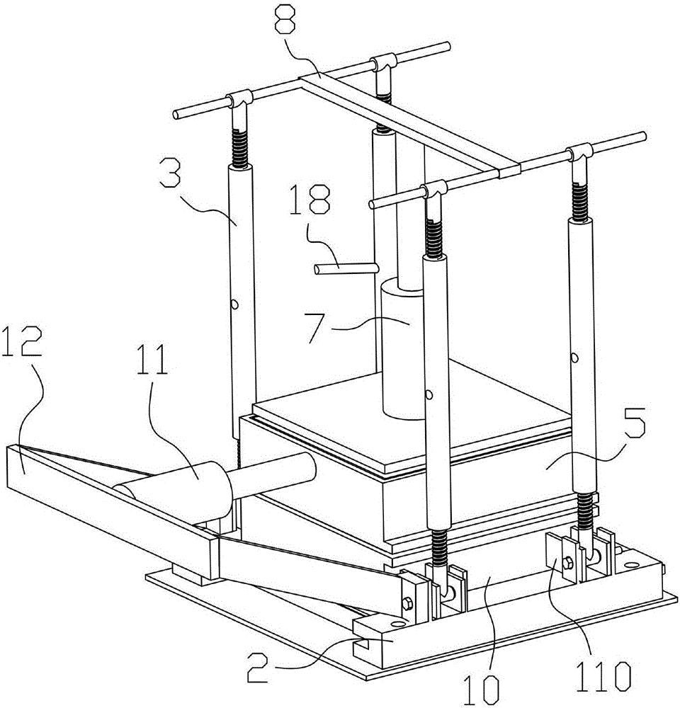
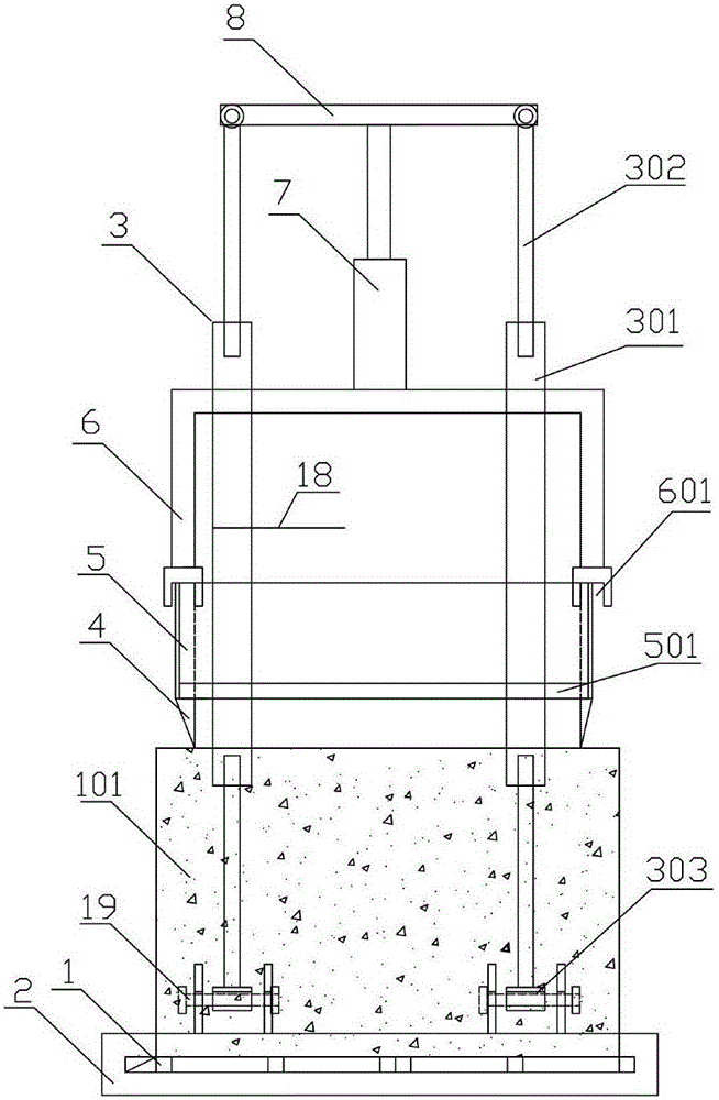
[0050] A soil preparation device for on-site soil direct shear test, comprising preparation components and loading components,

[0051] Preparation assembly: including a bottom frame, a bottom plate 1, a telescopic assembly and an upper cutting box 5, the telescopic assembly is hinged on the bottom frame, the bottom plate 1 is movably installed in the bottom frame, and the upper cutting box 5 is located in the telescopic assembly;

[0052] Loading assembly: including a first jack 7, a force transmission frame 6, a fixed frame 8 fixedly connected to the top of the telescopic assembly, one end of the first jack 7 is fixedly connected to the fixed frame 8, and the other end is against the force transmission On the end face of the frame 6 , the end of the force transmission frame 6 away from the first jack 7 abuts against the upper cutting box 5 .

[0053] Further, the force transmission frame 6 is in an "n" shape, and a clamping slot 601 is respectively fixed at two ends of the f...


PUM


Abstract

The invention discloses a device and method for preparation of a soil body for site soil body direct shear test and direct shear test. The device comprises a preparation assembly and a loading assembly. The preparation assembly comprises a bottom frame, a bottom plate, a telescopic assembly and an upper cutting box. The telescopic assembly is hinged to the bottom frame. The bottom plate is movably arranged in the bottom frame. The upper cutting box is located in the telescopic assembly. The loading assembly comprises a first jack, a force transferring frame, and a fixed frame fixedly connected to the top end of the telescopic assembly. One end of the first jack is fixedly connected to the fixed frame, and the other end of the first jack abuts against the end face of the force transferring frame. The end, away from the first jack, of the force transferring frame abuts against the upper cutting box.

Description

technical field [0001] The invention relates to a device and method for soil preparation and direct shear test for on-site soil direct shear test. Background technique [0002] In recent years, the theory, design and construction of underground engineering and slope engineering have been deeply studied. Most of the deformation and failure of geotechnical engineering are caused by shear failure. It plays an important role in geotechnical engineering. In the test of testing the shear strength of rock and soil, the direct shear test has been widely used because of its simple operation method and clear principle. [0003] Due to the limitations of field test conditions and funds, the direct shear test of rock and soil mass is still dominated by small-scale laboratory tests. The advantage is that the boundary conditions are easy to control, and various methods such as direct shear test, triaxial test, and torsional shear test can be used to obtain the shear strength parameters ...

Claims


Application Information

Patent Timeline
Patent Type & Authority Applications(China)
IPC IPC(8): G01N1/28G01N3/24
CPCG01N1/286G01N3/24G01N2001/2873G01N2203/0025
Inventor 邓华锋胡亚运肖志勇李建林孙旭曙周美玲胡安龙李春波常德龙
Owner CHINA THREE GORGES UNIV
Learn More