Supercharge Your Innovation With Domain-Expert AI Agents!

Measuring device for retroreflection characteristics of solid materials

A technology of retroreflection and solid materials, which is applied in the direction of scattering characteristic measurement, measuring devices, and analysis materials, etc., which can solve the problems of large error in measurement results and weak retroreflection energy of instruments

Active Publication Date: 2019-03-12
HARBIN INST OF TECH
View PDF9 Cites 0 Cited by
  • Summary
  • Abstract
  • Description
  • Claims
  • Application Information

AI Technical Summary

Problems solved by technology

[0003] The purpose of the present invention is to solve the problem of large errors in the measurement results of the retroreflective properties of solid materials due to mutual shielding of instruments and weak retroreflective energy in existing methods, and to provide an accurate measurement device for retroreflective properties of solid materials

Method used


Image

  • Measuring device for retroreflection characteristics of solid materials
  • Measuring device for retroreflection characteristics of solid materials

Examples


specific Embodiment approach 1

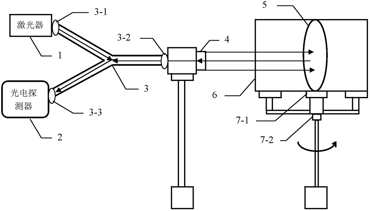
[0009] Specific implementation mode one: combine figure 1 and figure 2 Describe this embodiment, the device for measuring retroreflection characteristics of solid materials described in this embodiment includes a laser 1, a photodetector 2, an optical fiber circulator 3, an optical fiber collimator 4, and a light-shielding tube 6;

[0010] The laser light emitted by the laser 1 is incident on the No. 1 port 3-1 of the fiber circulator 3, and the laser light emitted from the No. 2 port 3-2 of the fiber circulator 3 is collimated by the fiber collimator 4 and then incident on the solid to be measured. The surface of the material 5, the laser light retroreflected by the surface of the solid material 5 to be measured is collimated by the fiber collimator 4 and then returns to the second port 3-2 of the fiber circulator 3, and from the third port 3-2 of the fiber circulator 3 3 The emitted laser light is incident on the detection surface of the photodetector 2, and the solid mate...

specific Embodiment approach 2

[0013] Specific implementation mode two: combination figure 1 and figure 2 Describe this embodiment. This embodiment is a further limitation of the device for measuring retroreflective characteristics of solid materials described in Embodiment 1. In this embodiment, the device also includes a rotating support, and the rotating support includes a dial 7 -2 and a rotatable turntable 7-1, the light shielding tube 6 is located on the turntable 7-1, and the dial 7-2 is used to display the rotation angle of the turntable 7-1.

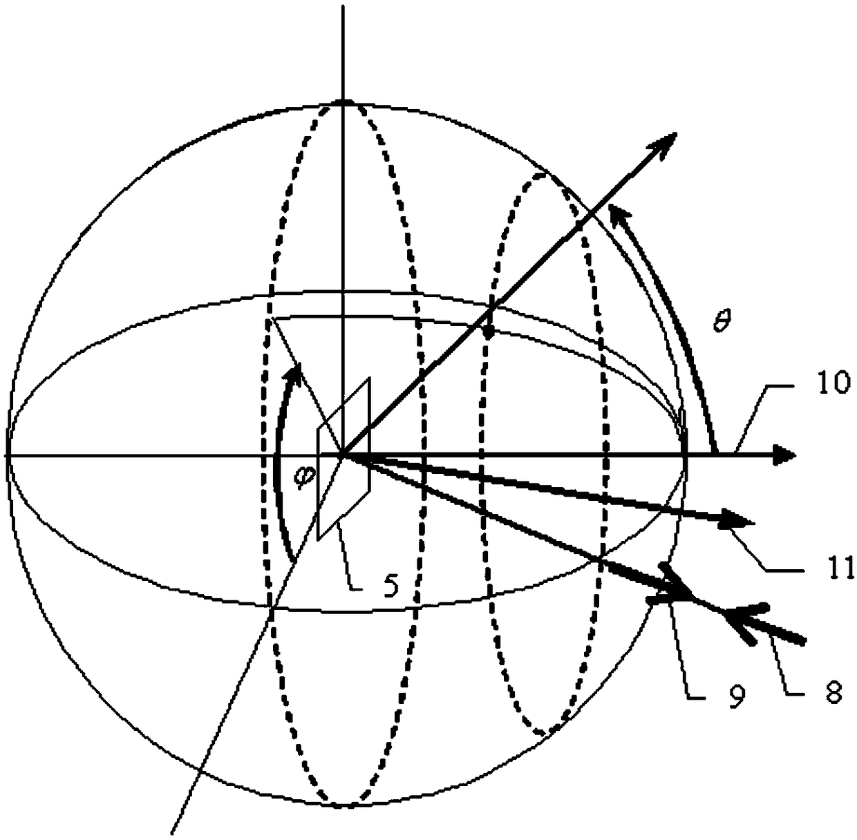
[0014] When the turntable 7-1 is adjusted to rotate, the angle of rotation can be read out according to the dial 7-2, and the retroreflectivity of the solid material 5 to be measured is measured at different angles of incidence. The rotation range of the turntable 7-1 is 0°~ 180 degrees, the test direction can achieve full coverage of the hemisphere space from 0 degrees to 180 degrees, and the laser incident / reflection angle can be in any direction in the h...

specific Embodiment approach 3

[0015] Specific implementation mode three: combination figure 2 Describe this embodiment, this embodiment is the further limitation to the solid material retroreflection characteristic measuring device described in embodiment two, in this embodiment, described turntable 7-1 is provided with slide rail, and light-shielding tube 6 can Move along the slide rail.

[0016] Adjusting the position of the light-shielding tube 6 according to the actual environment can better shield stray light.


PUM


Abstract

The invention provides a solid material reverse reflection characteristic measuring device and relates to the technology of precise measurement of solid material reverse reflection characteristics. The solid material reverse reflection characteristic measuring device aims at solving the problem that an existing method is large in measuring result error when used for measuring solid material reverse reflection characteristics. A laser emitted by a laser device is shot into a first port of an optical fiber circulator, the laser shot out of a second port of the optical fiber circulator is collimated with an optical fiber collimator and then shot to the surface of a solid material to be measured, the laser reversely reflected by the surface of the solid material to be measured is collimated with the optical fiber collimator and then returns to the second port of the optical fiber circulator, the laser shot out of a third port of the optical fiber circulator is shot to the detection surface of a photoelectric detector, the solid material to be measured is located in a light shielding cylinder, and the light shielding cylinder is located on a rotary tray. The solid material reverse reflection characteristic measuring device can measure laser energy in the micro-solid angle direction, and is high in measuring precision, easy to operate and suitable for optical measurement and laser active detection.

Description

technical field [0001] The invention relates to the field of optical measurement technology and laser active detection technology, in particular to the precise measurement technology of the retroreflection characteristics of solid materials. Background technique [0002] The reflection characteristics of the solid surface are the basic parameters for the calculation of surface-related radiation heat transfer and radiation detection, such as the analysis and calculation of radiation heat transfer in the boiler furnace, the analysis of radiation heat transfer in the engine engine, the performance analysis of the solar concentration system, the radiation heating and drying system, Radiation temperature measurement and ground object remote sensing all need to use the reflection characteristic parameters of the material surface, use the surface reflection characteristic parameters directly for heat transfer analysis, or use the surface reflection characteristic parameters as the b...

Claims


Application Information

Patent Timeline
Patent Type & Authority Patents(China)
IPC IPC(8): G01N21/47G01N21/01
CPCG01N21/01G01N21/4738G01N2021/0112G01N2021/4742
Inventor 帅永袁远陈翔谈和平武春风史要涛
Owner HARBIN INST OF TECH
Features
  • R&D
  • Intellectual Property
  • Life Sciences
  • Materials
  • Tech Scout
  • Unparalleled Data Quality
  • Higher Quality Content
  • 60% Fewer Hallucinations
Learn More