Error-separation-mode-based regional pseudo-range differential enhanced positioning method of GNSS

A pseudo-range differential and enhanced positioning technology, which is applied in satellite radio beacon positioning systems, measuring devices, instruments, etc., can solve the problems of difficulty in further improving positioning accuracy, high complexity of system implementation, and poor accuracy of grid ionosphere

Active Publication Date: 2016-08-24
ACAD OF OPTO ELECTRONICS CHINESE ACAD OF SCI
View PDF5 Cites 21 Cited by
  • Summary
  • Abstract
  • Description
  • Claims
  • Application Information

AI Technical Summary

Problems solved by technology

[0004] Wide-area enhancement broadcasts satellite orbit error, satellite clock error, and grid ionospheric error correction information in real time, and uses a vector method to correct user ranging errors; however, due to the significant regional characteristics of the ionosphere, the grid ionosphere accuracy is usually lower than A

Method used


Image

  • Error-separation-mode-based regional pseudo-range differential enhanced positioning method of GNSS
  • Error-separation-mode-based regional pseudo-range differential enhanced positioning method of GNSS
  • Error-separation-mode-based regional pseudo-range differential enhanced positioning method of GNSS

Examples


Embodiment 1

[0055] Embodiment 1, a kind of GNSS regional pseudo-range differential enhanced positioning method based on error separation mode, comprises the following steps:

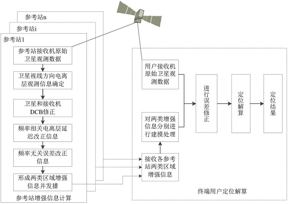
[0056] Step 1. The global satellite navigation system GNSS regional pseudo-range differential enhanced positioning adopts n reference stations and one end user; any one of the reference stations has its receiver r receive the original satellite observation data, and then perform the following processing to obtain the reference station r The error vector correction number of satellite s; the original satellite observation data includes pseudo-range observation and carrier phase observation.

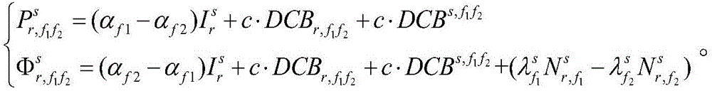
[0057] S101. Establish the GNSS non-difference observation equation, wherein the ionospheric delay error, hardware delay deviation and integer ambiguity are frequency-dependent items, and other error items are frequency-independent items, through the geometry of observations of the same type at two or more frequencies The irrele...

Embodiment 2

[0063] Embodiment 2. On the basis of Embodiment 1, this embodiment uses specific examples to describe Embodiment 1 in detail, and the parameters are only used as examples for convenience, and do not involve limitations on Embodiment 1.

[0064] Step 1. Obtain the original satellite observation data of the receiver of the reference station, and obtain the error vector correction number of the reference station r with respect to the satellite s after processing.

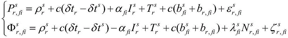
[0065] Generally, the pseudorange and carrier phase observation equations of the GNSS non-difference observation model are:

[0066] P r , f i s = ρ r s ...


PUM


Abstract

The invention discloses an error-separation-mode-based regional pseudo-range differential enhanced positioning method of a global navigation satellite system (GNSS). The method comprises: for regional pseudo-range differential enhanced positioning of a GNSS, n reference stations and a terminal user are employed; a receiver of any reference station r receives observation data of a satellite s, and after processing, an error vector correction number of the satellite s on the reference station r is obtained; each reference station sends the obtained error vector correction number of the satellite s to the terminal user, distance weighted mean processing is carried out on a frequency relevant item error correction number of each reference station according to a base line distance between the reference station and the terminal user, and then the processed number adds to a frequency non-relevant item error correction number of one reference number to obtain a total error correction number; and then a pseudo-range measurement value adds to the total error correction number to obtain a corrected user pseudo range and then calculation is carried out according to a standard pseudo-range single-point positioning way so as to obtain a user position after error correction. With the method, the positioning performance of the single-frequency satellite navigation can be improved.

Description

technical field [0001] The invention relates to the technical field of global navigation satellite system (Global Navigation Satellite System, GNSS) differential enhanced positioning, and proposes a GNSS regional pseudorange differential enhanced positioning method based on error separation mode. Background technique [0002] Under normal circumstances, the existing satellite navigation terminals can be divided into two types: measurement type and navigation type; the former usually has higher positioning accuracy, but its volume is large and the cost is high, and it is only used in special industries such as surveying and mapping, earthquake, and meteorology; the latter Positioning accuracy is usually low, but it has the advantages of low cost, low power consumption, small size, and easy integration. It is widely used in public location services and has a huge number of potential users. Compared with measurement terminals, navigation terminals can usually only obtain single...

Claims


Application Information

Patent Timeline
IPC IPC(8): G01S19/41
CPCG01S19/41
Inventor 汪亮李子申袁洪赵姣姣周凯
Owner ACAD OF OPTO ELECTRONICS CHINESE ACAD OF SCI
Why Eureka
Try Eureka