Subarray antenna structure suitable for millimeter wave LOS MIMO and design method

A technology of antenna structure and design method, applied in antennas, antenna arrays, electrical components, etc., can solve problems such as large path loss, small propagation distance, and difficulty in utilizing MIMO technology, achieving low sensitivity, strong robustness, Guaranteed effect of stability

Active Publication Date: 2016-08-24
白盒子(上海)微电子科技有限公司
View PDF4 Cites 10 Cited by
  • Summary
  • Abstract
  • Description
  • Claims
  • Application Information

AI Technical Summary

Problems solved by technology

[0003] The latest breakthroughs in the research of low-cost semiconductor silicon technology and silicon germanium millimeter-wave integrated circuits have guaranteed the feasibility of millimeter-wave communication to a certain extent, but the unique propagation characteristics of millimeter-wave signals limit the use of some communication technologies
It is mainly manifested in two aspects. First, the large path loss leads to a small propagation distance, and the current applications are mainly concentrated indoors; second, the sparse scattering characteristics of the millimeter wave channel lead to insignificant multipath effects, and the LOS component dominates. Difficult to take advantage of MIMO technology
The 802.11ad standard has proposed the use of array antennas and beamforming technology to enhance the directivity of the transmit and receive beams, and use array gain to compensate for part of the path loss, but only a single data stream can be transmitted

Method used


Image

  • Subarray antenna structure suitable for millimeter wave LOS MIMO and design method
  • Subarray antenna structure suitable for millimeter wave LOS MIMO and design method
  • Subarray antenna structure suitable for millimeter wave LOS MIMO and design method

Examples


Embodiment Construction

[0026] Below in conjunction with specific embodiment, further illustrate the present invention in conjunction with accompanying drawing, it should be understood that these embodiments are only used to illustrate the present invention and are not intended to limit the scope of the present invention, after having read the present invention, those skilled in the art will understand various aspects of the present invention Modifications in equivalent forms all fall within the scope defined by the appended claims of this application.

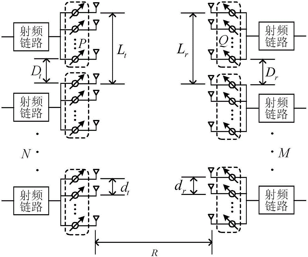
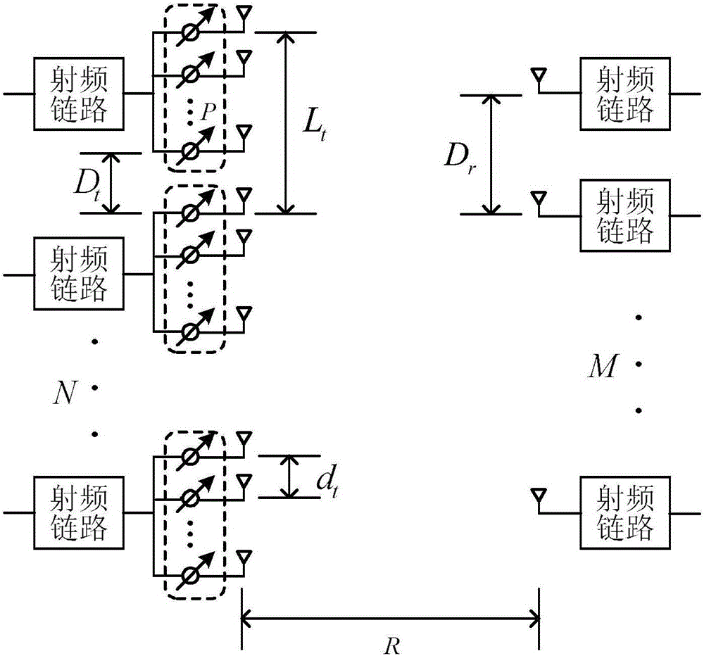
[0027] The embodiment of the present invention discloses a sub-array antenna structure suitable for millimeter-wave LOS MIMO channels. The transmitting end adopts an array transmission structure composed of phase shifters to form an antenna sub-array. Each antenna is connected to a phase shifter independently. A large number of antennas form a transmitting sub-array. The antennas in each sub-array are driven by the same radio frequency link. There is ...


PUM


Abstract

The invention discloses a subarray antenna structure suitable for LOS MIMO and a design method. A transmitting terminal employs an array emission structure of antenna subarrays formed by phase shifters, and a receiving terminal employs an oriented reception structure symmetric to the transmitting terminal or an asymmetric omnidirectional reception structure. Normalization antenna subarray interval conditions that meet the requirement are obtained through theoretical calculation, maximal effective freedom degree of a radio frequency equivalent channel in point-to-point LOS MIMO communication is realized, and the top and bottom limitations on effective freedom degree are reasonably estimated. Compared with a non-array antenna structure, the subarray antenna structure takes asymmetric and symmetric antenna subarrays into consideration. Array gain is provided, and a certain spatial multiplexing gain under a multipath-missing channel environment is ensured.

Description

technical field [0001] The invention belongs to the technical field of wireless communication, and relates to a sub-array antenna structure and a design method in millimeter-wave line-of-sight (Line Of Sight, LOS) multiple input multiple output (Multiple Input Multiple Output, MIMO) communication. Background technique [0002] As the number of users' wireless devices rapidly increases, the demand for data rates continues to expand, resulting in a spectrum crisis for existing wireless frequencies. mmWave is uniquely positioned to support wireless communications at very high data rates. Combined with MIMO technology, high-dimensional signal space can be used to transmit multiple independent data streams in parallel through different antennas, and spatial multiplexing technology can be used to improve spectral efficiency without increasing additional bandwidth and transmit power. [0003] The latest breakthroughs in low-cost semiconductor silicon technology and silicon germani...

Claims


Application Information

Patent Timeline
Patent Type & Authority Applications(China)
IPC IPC(8): H01Q21/00
CPCH01Q21/00
Inventor 何世文薛春林黄永明王海明杨绿溪洪伟
Owner 白盒子(上海)微电子科技有限公司
Why Eureka
Try Eureka