Motor driving system for vehicle bidirectional quasi-Z-source inverter

A motor drive system, source inverter technology, applied in the direction of electronic commutation motor control, control system, control generator, etc., can solve the problem that the upper and lower bridge arms cannot be conducted at the same time, cannot achieve high speed control, and increase electromagnetic noise of the system And other issues

Active Publication Date: 2016-08-24
TONGJI UNIV
View PDF5 Cites 7 Cited by
  • Summary
  • Abstract
  • Description
  • Claims
  • Application Information

AI Technical Summary

Problems solved by technology

[0003] 1. The bus voltage of the voltage-type inverter is the output voltage of the battery, which is limited by the battery voltage. When the car is climbing and accelerating, the voltage will drop when the battery is insufficient, resulting in insufficient output power of the motor. In order to improve Due to the soft characteristics of battery output, in fuel cell vehicles and electric commercial vehicles, a non-isolated BOOST circuit is usually added to the output end of the battery. After the BOOST circuit increases the voltage, it supplies the three-phase bridge inverter to drive the motor. The first-stage DC/DC inverter is a two-stage circuit, and the transmission efficiency of the system as a whole is low after two-stage conversion
[0004] 2. The upper and lower bridge arms of the...

Method used


Image

  • Motor driving system for vehicle bidirectional quasi-Z-source inverter
  • Motor driving system for vehicle bidirectional quasi-Z-source inverter
  • Motor driving system for vehicle bidirectional quasi-Z-source inverter

Examples


Embodiment Construction

[0053] The present invention will be described in detail below in conjunction with the accompanying drawings and specific embodiments. This embodiment is carried out on the premise of the technical solution of the present invention, and detailed implementation and specific operation process are given, but the protection scope of the present invention is not limited to the following embodiments.

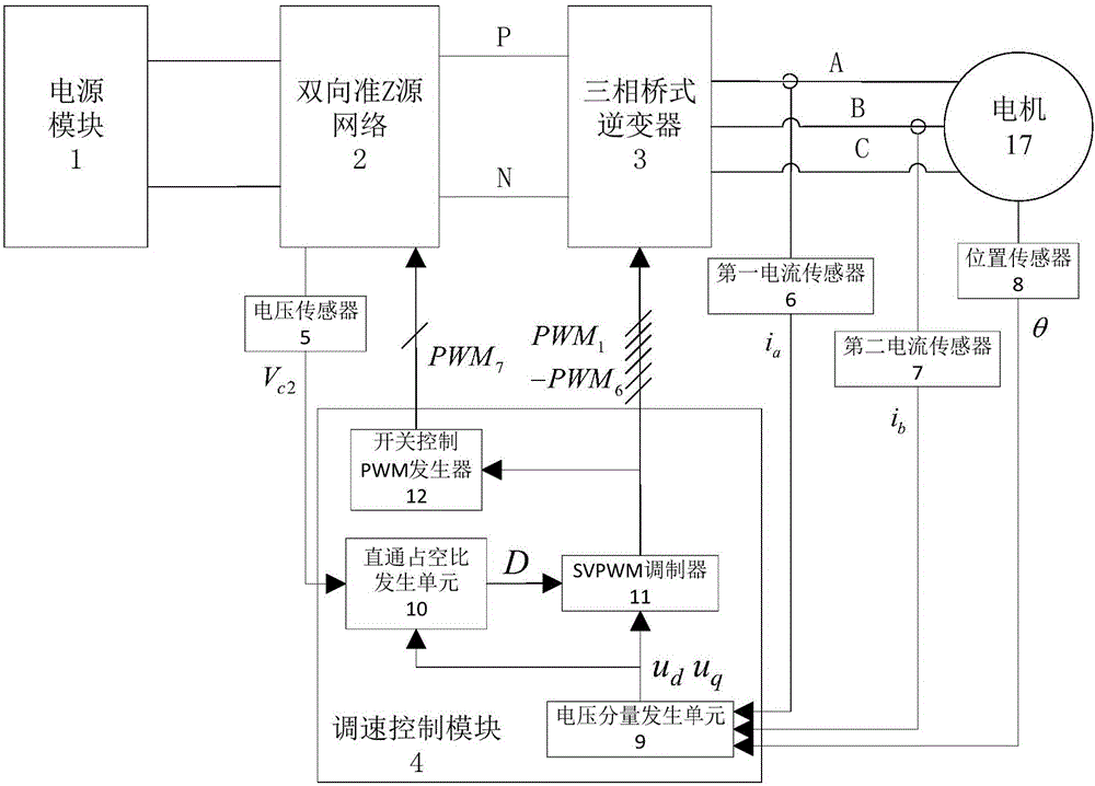
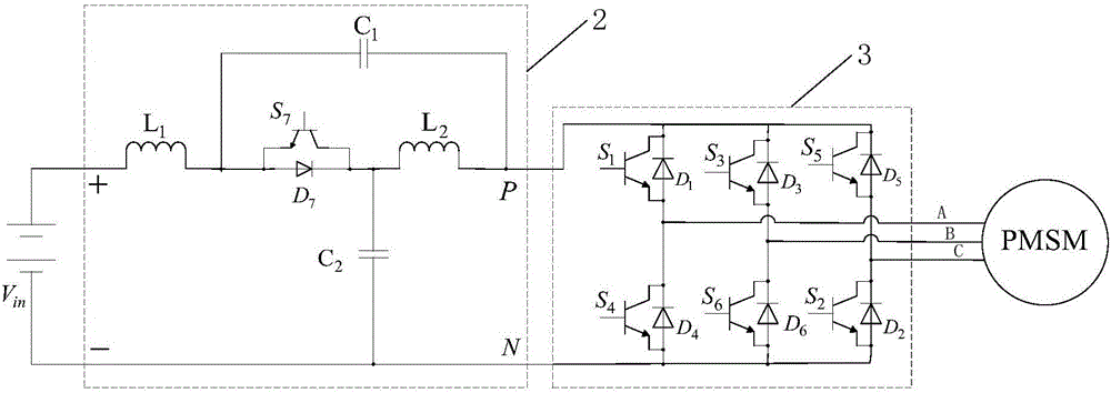
[0054] Such as figure 1 and figure 2 As shown, a vehicle bidirectional quasi-Z source inverter motor drive system includes a speed control module 4, a sensor unit, and a power module 1 connected in sequence, a bidirectional quasi-Z source front-stage passive network 2, and a three-phase bridge Inverter 3 and motor 17, bidirectional quasi-Z source front-stage passive network 2 and three-phase bridge inverter 3 constitute a bidirectional quasi-Z source inverter, which realizes boosting and frequency conversion speed regulation, and the speed regulation control module 4 Connect the se...


PUM


Abstract

The invention relates to a motor driving system for a vehicle bidirectional quasi-Z-source inverter. The motor driving system comprises a speed regulation control module, a sensor unit, and a power supply module, a bidirectional quasi-Z-source preceding-stage passive network, a three-phase bridge type inverter and a motor which are connected in sequence, wherein the bidirectional quasi-Z-source preceding-stage passive network and the three-phase bridge type inverter form the bidirectional quasi-Z-source inverter; the speed regulation control module is connected with the sensor unit and the bidirectional quasi-Z-source inverter separately; and the bidirectional quasi-Z-source preceding-stage passive network comprises inductors L1 and L2, capacitors C1 and C2, an IGBT switch tube S7 and a diode D7. Compared with the prior art, the bidirectional quasi-Z-source inverter system established by the invention, taken as the single-stage inverter system, can replace the two-stage conversion DC/DC and DC/AC conversion in the conventional electric driving field to avoid voltage fluctuation of the battery pack and maintain the stable and adjustable direct bus voltage; and in addition, the problem of dead time existing in the conventional inverter is prevented, so that the output voltage distortion can be lowered, and the torque pulsation and electromagnetic noises can be reduced.

Description

technical field [0001] The invention relates to the field of motor drive systems for vehicles, in particular to a motor drive system for bidirectional quasi-Z source inverters for vehicles. Background technique [0002] In the traditional motor drive system, the inverter is a voltage type inverter, which has the following disadvantages: [0003] 1. The bus voltage of the voltage-type inverter is the output voltage of the battery, which is limited by the battery voltage. When the car is climbing and accelerating, the voltage will drop when the battery is insufficient, resulting in insufficient output power of the motor. In order to improve Due to the soft characteristics of battery output, a non-isolated BOOST circuit is usually added to the output end of the battery in fuel cell vehicles and electric commercial vehicles. After the BOOST circuit increases the voltage, it is supplied to the three-phase bridge inverter to drive the motor. The level DC / DC inverter is a two-leve...

Claims


Application Information

Patent Timeline
IPC IPC(8): H02P21/05H02P27/12H02M7/797
CPCH02M7/797H02P21/05H02P27/12
Inventor 康劲松王硕蒋飞武松林
Owner TONGJI UNIV
Why Eureka
Try Eureka