
A laser-induced thermite welding method

An aluminothermic welding and laser-induced technology, which is applied in aluminothermic welding equipment, welding equipment, metal processing equipment, etc., can solve the problems of uneven flow of liquid molten iron, uneven mechanical and electrical properties, and easy occurrence of bubbles in welds, etc. problems, achieving fast and reliable ignition, precise and controllable energy distribution, and fast welding speed

Active Publication Date: 2018-01-16
呼和浩特市新城区创新创业服务中心
View PDF6 Cites 0 Cited by
  • Summary
  • Abstract
  • Description
  • Claims
  • Application Information

AI Technical Summary

Problems solved by technology

[0007] However, the current traditional thermite welding technology still has the following disadvantages: 1) It requires special solder thermite reaction tools and ignition tools, such as thermite pots, etc.
2) The flow of liquid molten iron is not uniform, and the thickness of the formed weld is not uniform, which leads to uneven mechanical and electrical properties in different areas of the joint; 3) Due to the incomplete metallurgical process, the weld is prone to defects such as bubbles and inclusions

Method used


Image

  • A laser-induced thermite welding method
  • A laser-induced thermite welding method
  • A laser-induced thermite welding method

Examples


Embodiment Construction

[0030] The present invention will be described in further detail below in conjunction with the accompanying drawings and specific embodiments.

[0031] The invention provides a laser-induced thermite welding method, comprising the following steps:

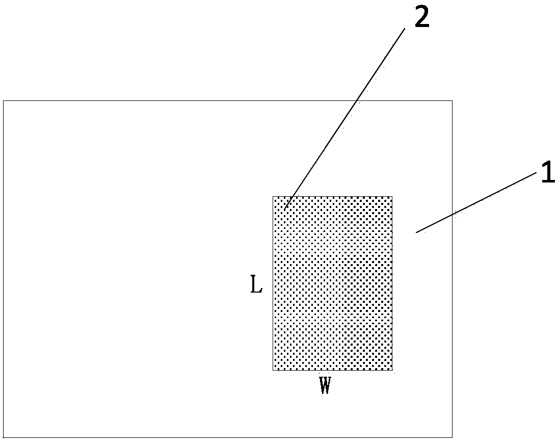
[0032] (1) if figure 1 As shown, a layer of thermite solder 2 is pre-laid on the position to be welded of the lower solder block 1 (base metal);

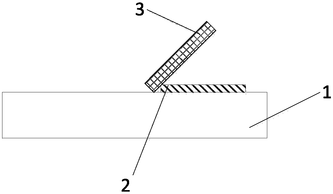
[0033] (2) if figure 2 As shown, the first end of the upper soldering block 3 is placed on the lower soldering block 1 and close to the position of the thermite solder 2, and the second end is kept at a distance from the lower soldering block 1, that is, the upper soldering block 3 and the lower soldering block 1 form a An included angle space with an included angle of 0 to 60 degrees;

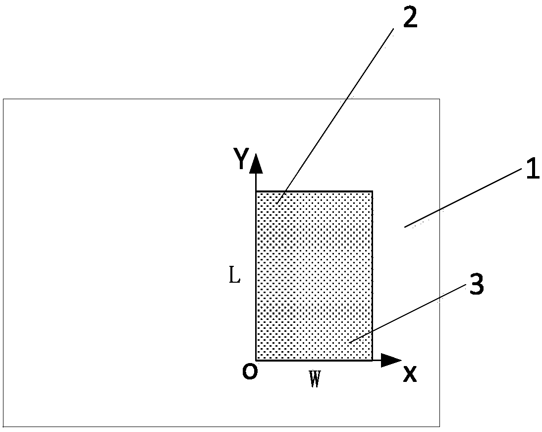
[0034] Such as image 3 As shown, the intersection line between the above solder block 3 and the lower solder block 1 is the Y axis, and one endpoint of the intersection line between the upper solde...


PUM

PropertyMeasurementUnit
thicknessaaaaaaaaaa

Abstract

The invention provides a laser-induced thermite welding method. The laser-induced thermite welding method comprises the following steps: (1), paving one layer of thermite welding flux on a lower welding block; (2), forming an included angle space between an upper welding block and the lower welding block; (3), obliquely shooting a laser beam from the included angle space, focusing at one end of the thermite welding flux, melting the thermite welding flux, also enabling the surfaces of the upper welding block and the lower welding block to melt for thin layers, forming a thermite welding flux bath and waiting that thermite reaction is fully carried out; (4), closing laser, with the press operation of the second end of the upper welding block, paving liquid welding flux promoting thermite reaction on the whole welding surface between the upper welding block and the lower welding block, extruding welding slags out of a welding seam, and enabling the upper welding block to be fully bonded with the lower welding block; and (5), after solidification, forming a welding joint. Through precise operation in a laser-induced thermite welding process, thermite reaction is sequentially carried out in a controlled manner, the liquid welding flux is uniformly paved, the overflow of air bubbles in the bath is facilitated, the welding slags are extruded out of the welding seam, and air bubble and inclusion defects easily occurring in a traditional thermite welding method are overcome.

Description

technical field [0001] The invention belongs to the technical field of welding, and in particular relates to a laser-induced thermite welding method. Background technique [0002] The basic principle of thermite welding is to reduce the iron in the iron oxide through the reduction reaction of aluminum and iron oxide. Once the thermite flux is ignited, the combustion will proceed by itself and spread to the entire reaction system, and the reaction products are Fe and Al 2 o 3 . The three kinds of aluminothermic chemical reaction equations are: [0003] 3FeO+2Al=3Fe+Al 2 o 3 +833.9kJ [0004] Fe 2 o 3 +2Al=Al 2 o 3 +2Fe+828.9kJ [0005] 3Fe 3 o 4 +8Al=4Al 2 o 3 +9Fe+3232.4kJ [0006] Thermite solder is a mixture of reducing agent metal aluminum, oxidizing iron oxide and other added alloying elements in a certain proportion. During welding, the aluminothermic solder is ignited by the igniter, causing a strong chemical reaction, which generates a large amount of...

Claims


Application Information

Patent Timeline
Patent Type & Authority Patents(China)
IPC IPC(8): B23K23/00
CPCB23K23/00
Inventor 于艳玲
Owner 呼和浩特市新城区创新创业服务中心
Learn More