
Vertical general assembly jig frame for container ship lashing bridge

A technology for container ships and lashing bridges, which is applied in the direction of berth, dry dock, transportation and packaging, etc., can solve the problems that cannot meet the needs of rapid, high-precision, scientific shipbuilding, difficult adjustment, deformation of lashing bridges, etc., to achieve Reduce the adjustment workload, reduce the intensity, and shorten the total group cycle

Active Publication Date: 2016-08-31
CHINA SHIPPING IND JIANGSU
View PDF7 Cites 7 Cited by
  • Summary
  • Abstract
  • Description
  • Claims
  • Application Information

AI Technical Summary

Problems solved by technology

Due to the high height of the lashing bridge, the height of the upper lashing bridge is generally greater than 9m for container ships with more than 10,000 TEUs. For the horizontal general group, taking a site with a length of 38m and a width of 48m as an example, only 4 lashing bridges can be placed at most The bridge occupies a large area of ​​the general group site; and the lashing bridge on the horizontal general group tire frame is lying flat, while the lashing bridge in the real ship state is standing, which requires the lashing bridge to be carried out once before being hoisted onto the ship. The overall 90-degree turn over, the process of turning over will cause a lot of deformation of the lashing bridge, which is difficult to adjust
This traditional general assembly method obviously cannot meet the needs of modern shipbuilding for rapid, high-precision, and scientific shipbuilding

Method used


Image

  • Vertical general assembly jig frame for container ship lashing bridge
  • Vertical general assembly jig frame for container ship lashing bridge
  • Vertical general assembly jig frame for container ship lashing bridge

Examples


Embodiment Construction

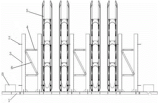
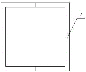
[0017] A container ship lashing bridge-vertical general group tire frame, comprising a strip tire frame 1, several frame backers and several square pipe fixing devices 2, the strip tire frame 1 is fixedly installed on the pre-embedded iron of the general group site, The several frame backers are evenly distributed on the strip tire frame 1, and the frame backers include two support rods 3 and two connecting rods 4 connecting the two support rods 3, and the lower ends of the two support rods 3 are fixedly installed on the The upper end of the strip tire frame 1, the square tube fixing device 2 is installed on the outside of two support rods 3, and the square tube fixing device 2 is used to fix the binding bridge square tube 5; There is a diagonal tie rod 6, which is located between the two connecting rods 4; the square tube fixing device 2 includes two square clips 7, the open ends of the two square clips 7 are fixedly connected, and one of the square clips The back side of 7 i...


PUM


Abstract

The invention relates to a vertical general assembly jig frame for a container ship lashing bridge. The vertical general assembly jig frame comprises a strip-shaped jig frame, a plurality of frame backers and a plurality of square tube fixing devices, wherein the strip-shaped jig frame is fixedly installed on a piece of embedded iron in a general assembly site; the plurality of frame backers are evenly distributed on the strip-shaped jig frame; each frame backer comprises two support rods and two connecting rods for connecting the two support rods, wherein the lower ends of the two support rods are fixedly installed at the upper end of the strip-shaped jig frame; each square tube fixing device is installed at the outer sides of the two corresponding support rods; the square tube fixing devices are used for fixing square tubes of the lashing bridge. The vertical general assembly jig frame is simple in structure, convenient in construction and short in general assembly period, and not only can greatly save the precious general assembly site, but also greatly reduces the on-board adjustment work load; furthermore, a turnover lifting lug is not needed during vertical general assembly, so that the strength of welding and grinding is greatly reduced; after the vertical general assembly jig frame is used, the process advancing aim of 'doing on-board operation after going ashore, and doing overhead operation at low altitude' is realized, the building period is shortened, and the working efficiency is increased.

Description

technical field [0001] The invention relates to a container ship lashing bridge tire frame, in particular to a container ship lashing bridge vertical general assembly tire frame, which belongs to the technical field of lashing bridges. Background technique [0002] In recent years, with the rapid development of container transportation, container ships are developing in the direction of large-scale. However, since the number of container layers stacked by large and ultra-large container ships reaches more than six layers, the lashing on the deck or hatch cover cannot meet the requirements. The number of stacked layers and stacking weight requirements, therefore, it is necessary to use a lashing bridge to meet this requirement. In order to ensure the safety, high precision and cycle of the lashing bridge assembly, after the lashing bridge is stripped off and sanded and painted in sections, it is necessary to carry out the assembly operation and finally hoist it onto the ship....

Claims


Application Information

Patent Timeline
Patent Type & Authority Applications(China)
IPC IPC(8): B63C5/02
CPCB63C5/02B63C2005/025
Inventor 任海兵李毅邹振山罗峥嵘
Owner CHINA SHIPPING IND JIANGSU
Learn More