Paraffin-prevention and viscosity-reduction rectifier of oil field flowing well

A rectifier and self-flowing well technology, which is applied in the direction of cleaning equipment, wellbore/well parts, earthwork drilling and production, etc., can solve the problems of reduced efficiency, high difficulty, and easy problems in sealing parts, so as to reduce the viscosity of the produced fluid and reduce the The cost of oil production and the effect of reducing workover operations

Pending Publication Date: 2016-08-31
邓海波
View PDF6 Cites 8 Cited by
  • Summary
  • Abstract
  • Description
  • Claims
  • Application Information

AI Technical Summary

Problems solved by technology

[0012] 2. There are great hidden dangers in safety and environmental protection
The pressure in the gushing well is at least a few MPa to tens of MPa or even higher. The installation and operation of the wax scraping equipment must frequently open and close several high-pressure valves, especially the reciprocating motion of the steel wire rope. The sealing part is prone to problems, causing oil, gas and water. Leakage pollutes the environment; if the well pressure is abnormal or improperly controlled, it is very easy to induce a blowout accident, causing heavy pollution and loss of personnel and property
[0013] 3. The labor intensity of the workers is high
Spontaneous well wax removal and descaling operations are difficult, intensive and dangerous. In many oil fields, it is necessary to operate at minus 20-30 degrees in winter and 40-50 degrees in summer. The work is very hard.
[0014] 4. Affect output, increase cost and reduce benefit

Method used


Image

  • Paraffin-prevention and viscosity-reduction rectifier of oil field flowing well
  • Paraffin-prevention and viscosity-reduction rectifier of oil field flowing well
  • Paraffin-prevention and viscosity-reduction rectifier of oil field flowing well

Examples


Embodiment Construction

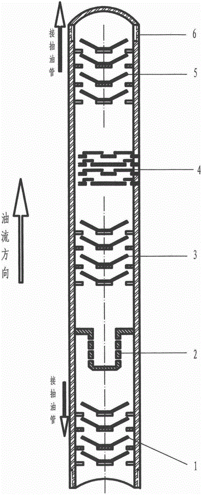
[0042] see figure 1 , In the present invention, in order to facilitate manufacture and installation, the three-section API tubing tube is used to install the components respectively, and then connect them to form a complete product. The first section of the tube is equipped with a first-stage vortex rectifier 1 and an impinging flow mixer 2; the second section of the tube is equipped with a second-stage vortex rectifier 3 and a sonic oscillator 4; the third section is equipped with a three-stage vortex rectifier 5. The three sections of pipe are connected by oilfield standard 27 / 8 inch pipe thread.

[0043] For the vortex rectifiers 1, 3, and 5 (ie, the first, second, and third stages) in the present invention, please refer to the structure Figure 5 , made of 2Cr18Ni9Ti steel; it is a circular bottom plate 18 with 6 rectangular channels 20. Above each channel, a baffle plate 19 at an angle of 30° to the central axis of the bottom plate is set, and the baffle plate is welded...


PUM


Abstract

A paraffin-prevention and viscosity-reduction rectifier of an oil field flowing well is suitable for extracting oil from an oil field high-pressure well, and the long-standing, big and difficult problem that paraffin and scale of a flowing well are scraped and removed through manual work since the beginning of the oil exploitation history is solved. The rectifier is a tubular tool and mounted in the position about one thousand meters under a paraffin-troubled well section of the well. A first-level vortex rectifier body, an impinging stream phase mixing device, a second-level vortex rectifier body, an impact type acoustic oscillator and a third-level vortex rectifier body are mounted in the rectifier from bottom to top, a large-cluster laminar-flow condensed phase state of flowing oil, gas and water can be treated to form a fine-cluster milky eddying turbulence phase state, all heterogeneous components are made to wrap one another, refining, scattering and shielding of paraffin crystals and scale crystals are achieved, the physical state, the physical property, the flow state and the flow speed of produced liquid are optimized, and the phenomenon that the well is blocked by gathered paraffin and scale crystals on the oil tube wall is fundamentally eliminated; and meanwhile, the viscosity of the produced liquid is greatly lowered, the in-well burble procedure is effectively prolonged, manual paraffin and scale scraping and removing are omitted, workover treatment is reduced, oil extraction cost is lowered, and production and efficiency are improved.

Description

1. Technical field: [0001] (1), the technical field of the present invention: [0002] Patent description Technical field: mechanical device and transportation technical field - mechanical component - G05G - control device or system only distinguished by mechanical characteristics. [0003] Catalogue of high-tech fields of the Ministry of Science and Technology: 8. High-tech transformation of traditional industries - (4) New machinery - 2. General machinery and new machinery. [0004] (2) Scope of application: [0005] The invention is suitable for oil production from blowout wells in onshore and offshore oilfields at home and abroad. [0006] (3) Function: [0007] The present invention adopts the technology of fluid flow velocity rectification, impinging flow miscibility technology and sonic oscillation homogenization technology to process the laminar condensed phase state of the flowing oil, gas and water large clusters into a fine cluster opacity turbulent phase state, ...

Claims


Application Information

Patent Timeline
Patent Type & Authority Applications(China)
IPC IPC(8): E21B28/00E21B37/00
CPCE21B28/00E21B37/00
Inventor 邓海波
Owner 邓海波
Why Eureka
Try Eureka